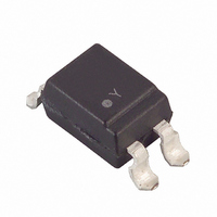
LTV-8141S Lite-On Electronics, LTV-8141S Datasheet - Page 11

LTV-8141S
Manufacturer Part Number
LTV-8141S
Description
OPTOISO 1CH AC-IN DARL OUT SMD
Manufacturer
Lite-On Electronics
Specifications of LTV-8141S
Maximum Fall Time
250 us
Maximum Input Diode Current
50 mA
Maximum Rise Time
300 us
Output Device
Darlington
Output Type
Transistor
Configuration
1
Input Type
AC, DC
Maximum Collector Emitter Voltage
35 V
Maximum Collector Emitter Saturation Voltage
1000 mV
Isolation Voltage
5000Vrms
Current Transfer Ratio
7500%
Maximum Forward Diode Voltage
1.4 V
Maximum Collector Current
80 mA
Maximum Power Dissipation
200 mW
Maximum Operating Temperature
+ 100 C
Minimum Operating Temperature
- 30 C
Package / Case
4-SMD
Number Of Channels
1
Voltage - Isolation
5000Vrms
Current Transfer Ratio (min)
20% @ 1mA
Current Transfer Ratio (max)
300% @ 1mA
Voltage - Output
35V
Current - Output / Channel
50mA
Current - Dc Forward (if)
±50mA
Vce Saturation (max)
200mV
Mounting Type
Surface Mount
Number Of Elements
1
Forward Voltage
1.4V
Forward Current
50mA
Collector-emitter Voltage
35V
Package Type
PDIP SMD
Collector Current (dc) (max)
80mA
Power Dissipation
200mW
Collector-emitter Saturation Voltage
1V
Fall Time
250000ns
Rise Time
300000ns
Pin Count
4
Mounting
Surface Mount
Operating Temp Range
-30C to 100C
Operating Temperature Classification
Commercial
Lead Free Status / RoHS Status
Lead free / RoHS Compliant
Lead Free Status / RoHS Status
Lead free / RoHS Compliant, Lead free / RoHS Compliant
Other names
160-1357-5
LTV8141S
LTV8141S
BNS-OD-C131/A4
Part No. : LTV-8141 / 8241 / 8441 ( M, S, S-TA1 )
CHARACTERISTICS CURVES
Fig.7 Relative Current Transfer Ratio
Fig.9 Collector Dark Current vs.
Fig.11 Frequency Response
vs. Ambient Temperature
Ambient Temperature
150
100
10
10
10
10
10
10
10
-10
-20
50
-10
-11
-5
-6
-7
-8
-9
0
0
0.02
-30
-25
LITE-ON TECHNOLOGY CORPORATION
V = 10V
CE
Ambient temperature Ta ( C)
Ambient temperature Ta ( C)
0.1
0
0
Frequency f (kHz)
25
25
1
50
50
Property of LITE-ON Only
1k
I = 1mA
V = 2V
F
10
CE
V = 2V
Ic= 2mA
Ta= 25 C
75
75
CE
o
o
100
o
100
100
100
Fig.8 Collector-emitter Saturation Voltage
Fig.10 Response Time vs. Load
Test Circuit for Response Time
Test Circuit for Frequency Response
Input
Resistance
vs. Ambient Temperature
R
500
200
100
1.0
0.8
0.6
0.4
0.2
0.5
0.2
50
20
10
D
0
1
5
2
0.05
-20
V = 2V
Ic= 10mA
Ta= 25 C
CE
Ambient temperature Ta ( C)
0.1 0.2
Load resistance R (k )
R
0
o
L
td
Vcc
ts
20
Output
R
D
0.5
tr
Output
40
Input
tf
1
td
60
L
R
2
tr
I = 20mA
Ic= 5mA
L
Vcc
F
Page : 11 of 12
80
o
5
ts
Output
100
tf
10
10%
90%


