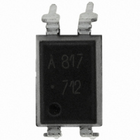
HCPL-817-000E Avago Technologies US Inc., HCPL-817-000E Datasheet - Page 6

HCPL-817-000E
Manufacturer Part Number
HCPL-817-000E
Description
OPTOCOUPLER TRANS-OUT 4-DIP
Manufacturer
Avago Technologies US Inc.
Datasheet
1.HCPL-817-300E.pdf
(7 pages)
Specifications of HCPL-817-000E
Output Type
Transistor
Input Type
DC
Package / Case
4-DIP (0.300", 7.62mm)
Number Of Channels
1
Voltage - Isolation
5000Vrms
Current Transfer Ratio (min)
50% @ 5mA
Current Transfer Ratio (max)
600% @ 5mA
Voltage - Output
70V
Current - Output / Channel
50mA
Current - Dc Forward (if)
50mA
Vce Saturation (max)
200mV
Mounting Type
Through Hole
Forward Current
50 mA
Maximum Fall Time
18 us
Maximum Input Diode Current
50 mA
Maximum Reverse Diode Voltage
6 V
Maximum Rise Time
18 us
Output Device
Transistor
Configuration
1
Maximum Collector Emitter Voltage
35 V
Maximum Collector Emitter Saturation Voltage
200 mV
Isolation Voltage
5000 Vrms
Current Transfer Ratio
600 %
Maximum Forward Diode Voltage
1.4 V
Maximum Collector Current
50 mA
Maximum Power Dissipation
200 mW
Maximum Operating Temperature
+ 100 C
Minimum Operating Temperature
- 30 C
Number Of Elements
1
Reverse Breakdown Voltage
6V
Forward Voltage
1.4V
Collector-emitter Voltage
35V
Package Type
PDIP
Collector Current (dc) (max)
50mA
Power Dissipation
200mW
Collector-emitter Saturation Voltage
0.2V
Fall Time
18000ns
Rise Time
18000ns
Pin Count
4
Mounting
Through Hole
Operating Temp Range
-30C to 100C
Operating Temperature Classification
Commercial
No. Of Channels
1
Optocoupler Output Type
Phototransistor
Input Current
20mA
Output Voltage
70V
Opto Case Style
DIP
No. Of Pins
4
Breakdown Voltage
70V
Rohs Compliant
Yes
Lead Free Status / RoHS Status
Lead free / RoHS Compliant
Lead Free Status / RoHS Status
Lead free / RoHS Compliant, Lead free / RoHS Compliant
Other names
516-1585-5
Available stocks
Company
Part Number
Manufacturer
Quantity
Price
Part Number:
HCPL-817-000E
Manufacturer:
AVAGO/安华高
Quantity:
20 000
Figure 4. Forward current vs. forward voltage.
Figure 6. Collector current vs. collector-emitter voltage.
Figure 8. Collector-emitter saturation voltage vs. temperature.
6
50
40
30
20
10
500
200
100
50
20
10
0
5
2
1
0.16
0.14
0.12
0.10
0.08
0.06
0.04
0.02
0
0
0
-25
I
F
1
= 25 mA
I
F
0.5
= 30 mA
T
T
T
A
A
A
V
2
= 75°C
= 50°C
= 25°C
CE
0
– COLLECTOR-EMITTER VOLTAGE – V
T
V
A
F
1.0
– AMBIENT TEMPERATURE – °C
3
– FORWARD VOLTAGE – V
I
F
= 20 mA
25
I
I
F
F
I
4
F
= 15 mA
= 10 mA
= 5 mA
1.5
5
50
2.0
6
T
T
A
A
= 0°C
= -25°C
7
75
I
I
F
C
2.5
= 20 mA
= 1 mA
T
P
A
C
= 25°C
(MAX.)
8
100
3.0
9
Figure 5. Current transfer ratio vs. forward current.
Figure 7. Relative current transfer ratio vs. temperature.
Figure 9. Collector dark current vs. temperature.
150
100
200
180
160
140
120
100
10
10
80
60
40
20
50
10
10
10
10
10
0
0
-10
-11
-30
-5
-6
-7
-8
-9
1
-25
V
CE
= 20 V
2
0
0
T
A
T
I
A
F
– AMBIENT TEMPERATURE – °C
– AMBIENT TEMPERATURE – °C
– FORWARD CURRENT – mA
25
25
5
10
50
50
20
75
75
I
V
V
T
F
A
CE
CE
= 5 mA
= 25°C
= 5 V
= 5 V
100
100
50


