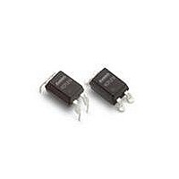
HCPL-817-50AE Avago Technologies US Inc., HCPL-817-50AE Datasheet - Page 5

HCPL-817-50AE
Manufacturer Part Number
HCPL-817-50AE
Description
ISOLAT 5KVRMS 1CH TRANS 4-SMD GW
Manufacturer
Avago Technologies US Inc.
Datasheet
1.HCPL-817-300E.pdf
(7 pages)
Specifications of HCPL-817-50AE
Output Type
Transistor
Input Type
DC
Package / Case
4-SMD Gull Wing
Mounting Type
Surface Mount, Gull Wing
Voltage - Output
70V
Number Of Channels
1
Current - Output / Channel
50mA
Current - Dc Forward (if)
50mA
Voltage - Isolation
5000Vrms
Vce Saturation (max)
200mV
Current Transfer Ratio (max)
160% @ 5mA
Current Transfer Ratio (min)
80% @ 5mA
Maximum Fall Time
18 us
Maximum Input Diode Current
50 mA
Maximum Reverse Diode Voltage
6 V
Maximum Rise Time
18 us
Output Device
Transistor
Configuration
1
Maximum Collector Emitter Voltage
35 V
Maximum Collector Emitter Saturation Voltage
200 mV
Isolation Voltage
5000 Vrms
Current Transfer Ratio
600 %
Maximum Forward Diode Voltage
1.4 V
Maximum Collector Current
50 mA
Maximum Power Dissipation
200 mW
Maximum Operating Temperature
+ 100 C
Minimum Operating Temperature
- 30 C
Lead Free Status / RoHS Status
Lead free / RoHS Compliant
Lead Free Status / RoHS Status
Lead free / RoHS Compliant, Lead free / RoHS Compliant
Available stocks
Company
Part Number
Manufacturer
Quantity
Price
Company:
Part Number:
HCPL-817-50AE
Manufacturer:
ALTERA
Quantity:
1 000
Part Number:
HCPL-817-50AE
Manufacturer:
AVAGO/安华高
Quantity:
20 000
Part Number:
HCPL-817-50AE/HCPL817-50AE
Manufacturer:
AVAGO/安华高
Quantity:
20 000
Electrical Specifications (T
* CTR =
Figure 1. Forward current vs. temperature.
Figure 3. Collector-emitter saturation voltage vs. forward current.
5
Parameter
Forward Voltage
Reverse Current
Terminal Capacitance
Collector Dark Current
Collector-Emitter Breakdown Voltage
Emitter-Collector Breakdown Voltage
Collector Current
*Current Transfer Ratio
Collector-Emitter Saturation Voltage
Response Time (Rise)
Response Time (Fall)
Cut-off Frequency
Isolation Resistance
Floating Capacitance
60
50
40
30
20
10
0
-30
6
5
4
3
2
1
0
0
I
I
C
F
x 100%
0
T
A
– AMBIENT TEMPERATURE – °C
I
F
25
– FORWARD CURRENT – mA
5
A
= 25°C)
50
I
I
I
I
I
C
C
C
C
C
= 0.5 mA
= 1 mA
= 3 mA
= 5 mA
= 7 mA
75
10
Symbol
V
I
C
CTR
V
t
t
f
R
C
BV
BV
I
R
I
C
c
r
f
CEO
F
t
CE(sat)
iso
f
CEO
ECO
100
T
A
= 25°C
Min.
–
–
–
–
70
6
2.5
50
–
–
–
–
5 x 10
–
125
15
10
Figure 2. Collector power dissipation vs. temperature.
Typ.
1.2
–
30
–
–
–
–
–
0.1
4
3
80
1 x 10
0.6
200
150
100
50
0
-30
11
Max.
1.4
10
250
100
–
–
30
600
0.2
18
18
–
–
1.0
0
T
A
– AMBIENT TEMPERATURE – °C
25
Units
V
μA
pF
nA
V
V
mA
%
V
μs
μs
KHz
Ω
pF
50
Test Conditions
I
V
V = 0, f = 1 KHz
V
I
I
I
R
I
V
R
V
R
DC 500 V
40 ~ 60% R.H.
V = 0, f = 1 MHz
F
C
E
F
F
R
CE
BE
CE
L
CC
L
= 20 mA
= 10 μA
= 5 mA, V
= 20 mA, I
= 0.1 mA
= 100 Ω
= 100 Ω, –3 dB
75
= 4 V
= ∞
= 2 V, I
= 20 V
= 5 V, I
C
C
100
CE
= 2 mA
C
= 2 mA
= 1 mA
= 5 V,
125


