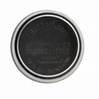
DS1921G-F5# Maxim Integrated Products, DS1921G-F5# Datasheet - Page 14

DS1921G-F5#
Manufacturer Part Number
DS1921G-F5#
Description
IBUTTON THERMOCHRON F5
Manufacturer
Maxim Integrated Products
Series
iButton®r
Datasheet
1.DS1921G-F5.pdf
(42 pages)
Specifications of DS1921G-F5#
Rohs Information
IButton RoHS Compliance Plan
Memory Size
512B
Memory Type
NVSRAM (Non-Volatile SRAM)
Ic Output Type
Digital
Sensing Accuracy Range
± 1.3°C
Supply Current
10µA
Supply Voltage Range
2.8V To 5.25V
Termination Type
Quick Connect
Operating Temperature Range
-40°C To +85°C
Supply Voltage Min
2.8V
Rohs Compliant
Yes
Filter Terminals
Quick Connect
Accuracy %
1°C
Lead Free Status / RoHS Status
Lead free / RoHS Compliant
Available stocks
Company
Part Number
Manufacturer
Quantity
Price
Thermochron iButton
The DS1921G is set up for its operation by writing
appropriate data to its special function registers that
are located in the register page. Several functions that
are controlled by a single bit only are combined into a
single byte called the Control register (address 020Eh).
This register can be read and written. If the device is
programmed for a mission, writing to the Control regis-
ter ends the mission and changes the register contents.
The functional assignments of the individual bits are
explained below. Bit 5 has no function. It always reads
0 and cannot be written to 1.
Bit 7: Enable Oscillator (EOSC). This bit controls the
crystal oscillator of the RTC. When set to logic 0, the
oscillator starts operation. When written to logic 1, the
oscillator stops and the device is in a low-power data-
retention mode. This bit must be 0 for normal opera-
tion. The RTC must have advanced at least 1 second
before a Mission Start is accepted.
Bit 6: Memory Clear Enable (EMCLR). This bit needs
to be set to logic 1 to enable the Clear Memory func-
tion, which is invoked as a memory function command.
The timestamp, histogram memory as well as the
Mission Timestamp, Mission Samples Counter, Mission
Start Delay, and Sample Rate are cleared only if the
Clear Memory command is issued with the next
access to the device. The EMCLR bit returns to 0 as
the next memory function command is executed.
Bit 4: Enable Mission (EM). This bit controls whether
the DS1921G begins a mission as soon as the sample
rate is written. To enable the device for a mission, this
bit must be 0.
Bit 3: Rollover Enable/Disable (RO). This bit controls
whether the temperature logging memory is overwritten
with new data or whether data logging is stopped once
the memory is filled with data during a mission. Setting
this bit to a 1 enables the rollover and data logging
continues at the beginning, overwriting previously col-
lected data. Clearing this bit to 0 disables the rollover
14
ADDRESS
020Eh
______________________________________________________________________________________
EOSC
BIT 7
EMCLR
BIT 6
Control Register
BIT 5
0
BIT 4
EM
and no further temperature values are stored in the
temperature logging memory once it is filled with data.
This does not stop the mission. The device continues
measuring temperatures and updating the histogram
and alarm timestamps and durations.
Bit 2: Temperature Low Alarm Search (TLS). If this
bit is 1, the device responds to a Conditional Search
ROM command if, during a mission, the temperature
has reached or is lower than the Low Temperature
Threshold stored at address 020Bh.
Bit 1: Temperature High Alarm Search (THS). If this
bit is 1, the device responds to a Conditional Search
ROM command if, during a mission, the temperature
has reached or is higher than the High Temperature
Threshold stored at address 020Ch.
Bit 0: Timer Alarm Search (TAS). If this bit is 1, the
device responds to a Conditional Search ROM com-
mand if, during a mission, a timer alarm has occurred.
Since a timer alarm cannot be disabled, the TAF flag
usually reads 1 during a mission. Therefore, it is advis-
able to set the TAS bit to a 0, in most cases.
The content of the Mission Start Delay Counter register
determines how many minutes the device waits before
starting the logging process. The Mission Start Delay
value is stored as an unsigned 16-bit integer number at
addresses 0212h (low byte) and 0213h (high byte). The
maximum delay is 65,535 minutes, equivalent to 45
days, 12 hours, and 15 minutes.
For a typical mission, the Mission Start Delay is 0. If a
mission is too long for a single DS1921G to store all
temperature readings at the selected sample rate, one
can use several devices, staggering the Mission Start
Delay to record the full period. In this case, the rollover
enable (RO) bit in the Control register (address 020Eh)
must be set to 0 to prevent overwriting of the recorded
temperature log after the data-log memory is full. See
the Mission Start and Logging Process section and
Figure 11 for details.
BIT 3
RO
Mission Start Delay Counter
BIT 2
TLS
Control Register Map
BIT 1
THS
BIT 0
TAS


