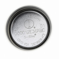
DS1923-F5# Maxim Integrated Products, DS1923-F5# Datasheet - Page 22

DS1923-F5#
Manufacturer Part Number
DS1923-F5#
Description
IBUTTON TEMP/HUMIDITY LOGGER F5
Manufacturer
Maxim Integrated Products
Series
iButton®r
Datasheet
1.DS1923-F5.pdf
(55 pages)
Specifications of DS1923-F5#
Rohs Information
IButton RoHS Compliance Plan
Memory Size
512B
Memory Type
NVSRAM (Non-Volatile SRAM)
Lead Free Status / RoHS Status
Lead free by exemption / RoHS compliant by exemption
Available stocks
Company
Part Number
Manufacturer
Quantity
Price
Hygrochron Temperature/Humidity Logger
iButton with 8KB Data-Log Memory
The fastest way to determine whether a programmed
temperature or humidity threshold was exceeded during
a mission is through reading the Alarm Status register.
In a networked environment that contains multiple
DS1923 iButtons, the devices that encountered an alarm
can quickly be identified by means of the Conditional
Search ROM command (see the 1-Wire ROM Function
Commands section). The humidity and temperature
alarm only occurs if enabled (see the Temperature
Sensor Alarm and Humidity Alarm sections). The BOR
alarm is always enabled.
Bit 7: Battery-On Reset Alarm (BOR). If this bit reads
1, the device has performed a power-on reset. This
indicates that the device has experienced a shock big
enough to interrupt the internal battery power supply.
The device can still appear functional, but it has lost its
factory calibration. Any data found in the data-log
memory should be disregarded.
Bit 3: Humidity High Alarm Flag (HHF). If this bit
reads 1, there was at least one humidity reading during
a mission revealing a value equal to or higher than the
value in the Humidity High Alarm register. A forced
conversion can affect the HHF bit.
Bit 2: Humidity Low Alarm Flag (HLF). If this bit reads
1, there was at least one humidity reading during a mis-
sion revealing a value equal to or lower than the value
in the Humidity Low Alarm register. A forced conversion
can affect the HLF bit.
Bit 1: Temperature High Alarm Flag (THF). If this bit
reads 1, there was at least one temperature conversion
during a mission revealing a temperature equal to or
higher than the value in the Temperature High Alarm
register. A forced conversion can affect the THF bit.
This bit can also be set with the initial alarm in the
SUTA = 1 mode.
Bit 0: Temperature Low Alarm Flag (TLF). If this bit
reads 1, there was at least one temperature conversion
Note: There is only read access to this register. Bits 4 to 6 have no function. They always read 1. All five alarm status bits are cleared
simultaneously when the Clear Memory command is invoked. See the Memory and Control Function Commands section for details.
Note: There is only read access to this register. Bits 0, 2, 5, 6, and 7 have no function.
22
ADDRESS
ADDRESS
0214h
0215h
______________________________________________________________________________________
BIT 7
BIT 7
BOR
1
BIT 6
BIT 6
1
1
Alarm Status
BIT 5
BIT 5
1
0
WFTA
BIT 4
BIT 4
1
during a mission revealing a temperature equal to or
lower than the value in the Temperature Low Alarm reg-
ister. A forced conversion can affect the TLF bit. This
bit can also be set with the initial alarm in the SUTA = 1
mode.
The information in the General Status register tells the
host computer whether a mission-related command
was executed successfully. Individual status bits indi-
cate whether the DS1923 is performing a mission, wait-
ing for a temperature alarm to trigger the logging of
data or whether the data from the latest mission has
been cleared.
Bit 4: Waiting for Temperature Alarm (WFTA). If this
bit reads 1, the mission start upon temperature alarm
was selected and the Start Mission command was suc-
cessfully executed, but the device has not yet experi-
enced the temperature alarm. This bit is cleared after a
temperature alarm event, but is not affected by the
Clear Memory command. Once set, WFTA remains set
if a mission is stopped before a temperature alarm
occurs. To clear WFTA manually before starting a new
mission, set the high temperature alarm (address
0209h) to -40°C and perform a forced conversion.
Bit 3: Memory Cleared (MEMCLR). If this bit reads 1,
the Mission Timestamp, Mission Samples Counter, and
all the alarm flags of the Alarm Status register have
been cleared in preparation of a new mission. Executing
the Clear Memory command clears these memory sec-
tions. The MEMCLR bit returns to 0 as soon as a new
mission is started by using the Start Mission command.
The memory must be cleared for a mission to start.
Bit 1: Mission in Progress (MIP). If this bit reads 1, the
device has been set up for a mission and this mission is
still in progress. The MIP bit returns from logic 1 to logic
0 when a mission is ended. See the Start Mission [with
Password] [CCh] and Stop Mission [with Password]
[33h] sections.
MEMCLR
BIT 3
BIT 3
HHF
General Status Register Bitmap
Alarm Status Register Bitmap
BIT 2
BIT 2
HLF
0
BIT 1
BIT 1
THF
MIP
General Status
BIT 0
BIT 0
TLF
0


