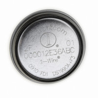
DS1973-F5+ Maxim Integrated Products, DS1973-F5+ Datasheet - Page 2

DS1973-F5+
Manufacturer Part Number
DS1973-F5+
Description
IBUTTON EEPROM 4KBit F5
Manufacturer
Maxim Integrated Products
Series
iButton®r
Datasheet
1.DS1973-F5.pdf
(3 pages)
Specifications of DS1973-F5+
Rohs Information
IButton RoHS Compliance Plan
Memory Size
512B
Memory Type
EEPROM
Lead Free Status / RoHS Status
Lead free / RoHS Compliant
DS1973
iButton DESCRIPTION
The DS1973 4Kb EEPROM iButton is a rugged read/write data carrier that identifies and stores relevant
information about the product or person to which it is attached. This information can be accessed with
minimal hardware, for example a single port pin of a micro-controller. The DS1973 consists of a factory-
lasered registration number that includes a unique 48-bit serial number, an 8-bit CRC, and an 8-bit
Family Code (23H) plus 4096 bits of EEPROM. The power to program and read the DS1973 is derived
entirely from the 1-Wire communication line. The memory is organized as sixteen pages of 256 bits each.
The 64-bit registration number provides a guaranteed unique identity which allows for absolute
traceability. Data is transferred serially via the 1-Wire protocol which requires only a single data lead and
a ground return. The durable MicroCan package is highly resistant to harsh environments such as dirt,
moisture, and shock. Its compact button-shaped profile is self-aligning with cup-shaped receptacles,
allowing the DS1973 to be used easily by human operators or automatic equipment. Accessories permit
the DS1973 to be mounted on printed circuit boards, plastic key fobs, photo-ID badges, ID bracelets, and
many other objects. Applications include work-in-progress tracking, electronic travelers, access control
and storage of calibration constants.
OVERVIEW
The block diagram in Figure 1 shows the relationships between the major control and memory sections of
the DS1973. The DS1973 has three main data components: 1) 64-bit lasered ROM, 2) 256-bit scratchpad,
and 3) 4096-bit EEPROM. The bus master must first provide one of the ROM function commands before
the memory functions become accessible. All data is read and written least significant bit first.
The DS1973 contains the same memory chip as the DS2433. For a full description of the logical
behavior, please refer to the DS2433 data sheet.
DS1973 BLOCK DIAGRAM Figure 1
2 of 3


