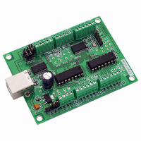
27969 Parallax Inc, 27969 Datasheet - Page 14

27969
Manufacturer Part Number
27969
Description
BOARD BISTEP MOTOR CTRLR USB
Manufacturer
Parallax Inc
Datasheet
1.27969.pdf
(21 pages)
Specifications of 27969
Motor Type
Stepper, Unipolar
Number Of Motors
2
Voltage - Output
15V
Voltage - Logic Supply
6.5 V ~ 15 V
Current - Output
1A
Termination Style
Screw Terminal
Product
Microcontroller Accessories
Lead Free Status / RoHS Status
Lead free / RoHS Compliant
For Use With
27964 - UNIPOLAR STEPPER MOTOR 12VDC
Lead Free Status / RoHS Status
Lead free / RoHS Compliant, Lead free / RoHS Compliant
Common Parallax Stamp Issue Summary
Common Parallax Stamp Issue Summary
Once the board has passed the above set of tests, you can connect it to your Stamp. The Stamp products are
usually connected to our board via the “TTL-Serial” technique, described earlier in this manual.
summary:
First Use
Make certain both the Stamp and the board's logic are run off of the same power
supply.
When you actually try to run your Stamp application, disconnect the “download”
programming RS232 cable from between the computer and the stamp.
Disable RS232 communications to the board.
Make certain that you have adjusted our sample code to match your stamp
product.
If this is not possible, make certain that the “GND” line of the stepper controller is connected to a
GND (also called Vss by Parallax) on the Parallax board. Using a common power supply for the
boards avoids ground referencing problems. This is the single most common cause of issues when
using the stamp. If separate supplies must be used, then you must be certain that you connect their
grounds together with a reasonable size wire, in order to make certain that both boards "float" at the
same potential. Otherwise, TTL signals will not be correctly interpreted, and serial communications
will fail.
We have often had issues with ground-distortion induced by leaving the serial cable (used to program
the stamp) connected while trying to have the stamp “talk” to a stepper controller board. Merely
unplugging the cable has always been enough to “fix” the problem.
Remove the JS jumper from our board (Jumper Serial) if that jumper is available (it is present on all of
our newer artworks which have RS232 or USB serial built in). If you have the BiStepA04, BiStepA05,
BiStep2A04 or SimStepA04, remove (and save) the 16-pin Max232 serial controller chip located right
by the 9 pin serial connector. Removal of the JS jumper or the Max232 chip is needed to avoid
connecting the outputs of two chips to each other. This generates what is called a "wired or", and can
cause eventual failure of the chips involved.
Different stamps require different settings for the "PortStepperBaud" parameter used in our samples.
When you edit the sample code for your system, you need to look for the line which contains the
"{$STAMP" command, and adjust it to match your stamp (such as BS2, BS2sx, etc.). This may also
be done by pressing the button in the Basic Stamp Editor that selects the type of stamp that you are
using. You then need to edit the line that defines the "PortStepperBaud" parameter to contain the
correct value for your stamp. Please refer to your stamp manual for the values. For some of the
stamps, the values are:
For example, to generate 9600 baud on a BS2sx, you need to have the PortStepperBaud line contain:
PortStepperBaud con 240 ' Baud rate to generate 9600 baud on BS2sx
BS2sx/BS2p
Stamp Unit
BS2/BS2e
9600 Baud
240
84
Peter Norberg Consulting, Inc.
2400 Baud
1021
396
Page 14
In


