BFC237111124 Vishay, BFC237111124 Datasheet - Page 24
BFC237111124
Manufacturer Part Number
BFC237111124
Description
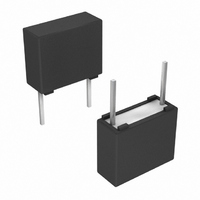
CAP FILM MKT .12UF 63VDC 10%
Manufacturer
Vishay
Series
MKT 371r
Datasheet
1.BFC237351155.pdf
(28 pages)
Specifications of BFC237111124
Capacitance
0.12µF
Voltage - Ac
40V
Voltage - Dc
63V
Dielectric Material
Polyester, Metallized
Tolerance
±10%
Operating Temperature
-55°C ~ 105°C
Mounting Type
Through Hole
Package / Case
Radial
Size / Dimension
0.394" L x 0.118" W (10.00mm x 3.00mm)
Height
0.315" (8.00mm)
Termination
PC Pins
Lead Spacing
0.300" (7.62mm)
Features
General Purpose
Lead Free Status / RoHS Status
Lead free / RoHS Compliant
Esr (equivalent Series Resistance)
-
Other names
2222 371 11124
222237111124
BC1680
BFC2 371 11124
BFC2 371 11124
222237111124
BC1680
BFC2 371 11124
BFC2 371 11124


APPLICATION NOTE AND LIMITING CONDITIONS
These capacitors are not suitable for mains applications as across-the-line capacitors without additional protection, as described
hereunder. These mains applications are strictly regulated in safety standards and therefore electromagnetic interference
suppression capacitors conforming the standards must be used.
To select the capacitor for a certain application, the following conditions must be checked:
1. The peak voltage (U
2. The peak-to-peak voltage (U
3. The voltage peak slope (dU/dt) shall not exceed the rated voltage pulse slope in an RC-circuit at rated voltage and without
4. The maximum component surface temperature rise must be lower than the limits (see graph max. allowed component
5. Since in circuits used at voltages over 280 V peak-to-peak the risk for an intrinsically active flammability after a capacitor
6. When using these capacitors as across-the-line capacitor in the input filter for mains applications or as series connected with
Voltage Conditions for 6 Above
EXAMPLE
C = 330 nF - 63 V used for the voltage signal shown in next drawing.
U
The ambient temperature is 35 °C
Checking conditions:
1. The peak voltage U
2. The peak-to-peak voltage 40 V is lower than 2√2 x 40 Vac = 113 U
3. The voltage pulse slope (dU/dt) = 40 V/100 µs = 0.4 V/µs
4. The dissipated power is 16.2 mW as calculated with fourier terms
5. Not applicable
6. Not applicable
Document Number: 28109
Revision: 08-Dec-08
P-P
ALLOWED VOLTAGES
Maximum continuous RMS voltage
Maximum temperature RMS-overvoltage (< 24 h)
Maximum peak voltage (V
ringing. If the pulse voltage is lower than the rated DC voltage, the rated voltage pulse slope may be multiplied by U
divided by the applied voltage.
For all other pulses following equation must be fulfilled:
T is the pulse duration
temperature rise).
breakdown (short circuit) increases, it is recommended that the power to the component is limited to 100 times the values
mentioned in the table: “Heat conductivity”
an impedance to the mains the applicant must guarantee that the following conditions are fulfilled in any case (spikes and
surge voltages from the mains included).
This is lower than 60 V/µs (see specific reference data for each version)
The temperature rise for W
This is lower than 15 °C temperature rise at 35 °C, according figure max. allowed component temperature rise
= 40 V; U
2
×
T
∫
0
⎛
⎝
dU
------- -
dt
⎞
⎠
2
P
×
= 35 V; T
dt U
<
Rdc
P
P
) shall not be greater than the rated DC voltage (U
O-P
= 35 V is lower than 63 Vdc
1
.
×
= 100 µs; T
) (< 2 s)
⎛
⎝
dU
------- -
dt
max.
⎞
⎠
P-P
rated
= 3.5 mm and pitch = 5 mm will be 16.2 mW/3.0 mW/°C = 5.4 °C
) shall not be greater than 2
2
= 200 µs
For technical questions, contact: dc-film@vishay.com
MKT Radial Potted Type
DC Film Capacitor
√
2 x U
Rac
T
1.25 x U
amb
1.6 x U
P-P
to avoid the ionisation inception level
MKT 371, MKT 372, MKT 373
U
≤ 85 °C
Rac
Rdc
Rdc
Rac
)
Vishay BCcomponents
See “Max. AC voltage as function
of temperature CBB952” per
85 °C < T
characteristics
1.3 x U
U
amb
Rac
Rdc
≤ 105 °C
www.vishay.com
Rdc
and
117
Related parts for BFC237111124
Image
Part Number
Description
Manufacturer
Datasheet
Request
R

Part Number:
Description:
357-036-542-201 CARDEDGE 36POS DL .156 BLK LOPRO
Manufacturer:
Vishay
Datasheet:
Part Number:
Description:
357-036-542-201 CARDEDGE 36POS DL .156 BLK LOPRO
Manufacturer:
Vishay
Datasheet:
Part Number:
Description:
357-036-542-201 CARDEDGE 36POS DL .156 BLK LOPRO
Manufacturer:
Vishay
Datasheet:
Part Number:
Description:
357-036-542-201 CARDEDGE 36POS DL .156 BLK LOPRO
Manufacturer:
Vishay
Datasheet:
Part Number:
Description:
357-036-542-201 CARDEDGE 36POS DL .156 BLK LOPRO
Manufacturer:
Vishay
Datasheet:
Part Number:
Description:
357-036-542-201 CARDEDGE 36POS DL .156 BLK LOPRO
Manufacturer:
Vishay
Datasheet:
Part Number:
Description:
357-036-542-201 CARDEDGE 36POS DL .156 BLK LOPRO
Manufacturer:
Vishay
Datasheet:
Part Number:
Description:
357-036-542-201 CARDEDGE 36POS DL .156 BLK LOPRO
Manufacturer:
Vishay
Datasheet:
Part Number:
Description:
357-036-542-201 CARDEDGE 36POS DL .156 BLK LOPRO
Manufacturer:
Vishay
Datasheet:
Part Number:
Description:
357-036-542-201 CARDEDGE 36POS DL .156 BLK LOPRO
Manufacturer:
Vishay
Datasheet:
Part Number:
Description:
357-036-542-201 CARDEDGE 36POS DL .156 BLK LOPRO
Manufacturer:
Vishay
Datasheet:
Part Number:
Description:
357-036-542-201 CARDEDGE 36POS DL .156 BLK LOPRO
Manufacturer:
Vishay
Datasheet:
Part Number:
Description:
357-036-542-201 CARDEDGE 36POS DL .156 BLK LOPRO
Manufacturer:
Vishay
Datasheet:
Part Number:
Description:
357-036-542-201 CARDEDGE 36POS DL .156 BLK LOPRO
Manufacturer:
Vishay
Datasheet:
Part Number:
Description:
357-036-542-201 CARDEDGE 36POS DL .156 BLK LOPRO
Manufacturer:
Vishay
Datasheet: