HFBR-4532 Avago Technologies US Inc., HFBR-4532 Datasheet - Page 6
HFBR-4532
Manufacturer Part Number
HFBR-4532
Description
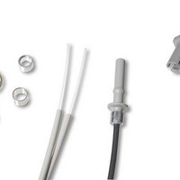
HDWR V-LINK CONN CRIMPLESS BLACK
Manufacturer
Avago Technologies US Inc.
Datasheet
1.HFBR-4521Z.pdf
(10 pages)
Specifications of HFBR-4532
Accessory Type
Connector
Lead Free Status / RoHS Status
Contains lead / RoHS non-compliant
For Use With/related Products
Plastic Optical Fiber, Versatile Link
Lead Free Status / Rohs Status
Lead free / RoHS Compliant
Available stocks
Company
Part Number
Manufacturer
Quantity
Price
Company:

Part Number:
HFBR-4532Z
Manufacturer:
Broadcom Limited
Quantity:
6


Step 3
Any excess fiber protruding from the connector end may
be cut off; however, the trimmed fiber should extend at
least 1.5 mm (0.06 in) from the connector end.
Insert the connector fully into the polishing fixture with
the trimmed fiber protruding from the bottom of the
fixture. This plastic polishing fixture can be used to polish
two simplex connectors or simplex latching connectors
simultaneously, or one duplex connector.
Note: The four dots on the bottom of the polishing fixture
are wear indicators. Replace the polishing fixture when any
dot is no longer visible. Typically, the polishing fixture can
be used 10 times; 10 duplex connectors or 20 simplex con
nectors, two at a time.
Place the 600 grit abrasive paper on a flat smooth surface,
pressing down on the connector, polish the fiber and the
connector using a figure eight pattern of strokes until the
connector is flush with the bottom of the polishing fixture.
Wipe the connector and fixture with a clean cloth or tissue.
6
Step 4
Place the flush connector and polishing fixture on the dull
side of the 3 µm pink lapping film and continue to polish
the fiber and connector for approximately 25 strokes. The
fiber end should be flat, smooth and clean.
This cable is now ready for use.
Note: Use of the pink lapping film fine polishing step results in
approximately 2 dB improvement in coupling performance
of either a transmitterreceiver link or a bulkhead/splice over
a 600 grit polish alone. This fine polish is comparable to the
Avago factory polish. The fine polishing step may be omitted
where an extra 2 dB of optical power is not essential, as with
short link lengths. Proper polishing of the tip of the fiber/con
nector face results in a tip diameter between 2.5 mm (0.098
in.) minimum and 3.2 mm (0.126 in.) maximum..
HFBR-4593 Polishing Kit
Related parts for HFBR-4532
Image
Part Number
Description
Manufacturer
Datasheet
Request
R

Part Number:
Description:
RECEIVER FIBER OPTIC 600NM 5MBD
Manufacturer:
Avago Technologies US Inc.
Datasheet:

Part Number:
Description:
XMITTER FIBER OPTIC 600NM 5MBD
Manufacturer:
Avago Technologies US Inc.
Datasheet:

Part Number:
Description:
XMITTER FIBER OPTIC 600NM 40KBD
Manufacturer:
Avago Technologies US Inc.
Datasheet:

Part Number:
Description:
XMITTER FIBER OPTIC 600NM 10MBD
Manufacturer:
Avago Technologies US Inc.
Datasheet:

Part Number:
Description:
Fiber Optic Transmitters, Receivers, Transceivers 1x9 622Mb/s SR ExtTe mp Txcvr Metal
Manufacturer:
Avago Technologies US Inc.
Part Number:
Description:
Fiber Optic Transmitters, Receivers, Transceivers 1x9 622Mb/s SR ExtTe mp Txcvr Metal
Manufacturer:
Avago Technologies US Inc.

Part Number:
Description:
125MBD 650NM RECEIVER IN HORIZ
Manufacturer:
Avago Technologies US Inc.
Datasheet:

Part Number:
Description:
FIBER OPTIC TX 125 MBD 650N
Manufacturer:
Avago Technologies US Inc.
Datasheet:

Part Number:
Description:
XMITTER FIBER OPTIC ST 1300NM
Manufacturer:
Avago Technologies US Inc.
Datasheet:

Part Number:
Description:
4+4 2.7G Plgb Txcvr Wo HS, Pb-free
Manufacturer:
Avago Technologies US Inc.
Datasheet:

Part Number:
Description:
OPTOCOUPLER GATE DRV 2A 16-SOIC
Manufacturer:
Avago Technologies US Inc.
Datasheet:
Part Number:
Description:
OPTOCOUPLER 2CH 2.5A 16-SOIC
Manufacturer:
Avago Technologies US Inc.
Datasheet:

Part Number:
Description:
OPTOCOUPLER GATE DRV 0.4A 16SOIC
Manufacturer:
Avago Technologies US Inc.
Datasheet:

Part Number:
Description:
OPTOCOUPLER 2.0A 250KHZ 8-DIP
Manufacturer:
Avago Technologies US Inc.
Datasheet:

Part Number:
Description:
OPTOCOUPLER 2.0A 250KHZ GW 8-SMD
Manufacturer:
Avago Technologies US Inc.
Datasheet: