HDSM-443B Avago Technologies US Inc., HDSM-443B Datasheet
HDSM-443B
Specifications of HDSM-443B


Related parts for HDSM-443B


HDSM-443B Summary of contents
Page 1
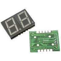
... HDSM-441x/443x 0.39” (10.0mm) Dual digit surface mount LED display Data Sheet Description The HDSM-441x/443x is a dual digit display of 0.39” (10.0mm) height. This device utilizes AlInGaP / GaAs chips and has a grey top surface with white segments. Ordering Information Red Green ...
Page 2
Pin Connection (Common Anode) PIN No Connection 1 CATHODE G 2 CATHODE DP 3 CATHODE A 4 CATHODE F 5 COMMON ANODE DIG2 6 CATHODE D 7 CATHODE E 8 CATHODE C 9 CATHODE B 10 COMMON ANODE DIG1 Internal ...
Page 3
Electrical / Optical Characteristics @ T Green Parameters Symbol Average Luminous Intensity I O Emissions Wavelength 'O Spectral Line Half-Width Forward Voltage, Per Segment V Reverse Current, Per Segment I Luminous Intensity Matching Ratio I Yellow Parameters Average Luminous Intensity ...
Page 4
Typical Electrical / Optical characteristic curves @ T Green G 1.0 . 0.5 0 400 450 500 550 WAVELENGTH(nm) Figure 1. Relative Luminous Intensity vs. Wavelength ...
Page 5
Yellow 1.0 0.5 0 400 450 500 550 WAVELENGTH(nm) Figure 1. Relative Intensity vs. Wavelength AMBIENT TEMPERATURE(°C) Figure 3. Allowable DC Current vs. Ambient Temperature 5 4 ...
Page 6
Red 1.0 0.5 0 400 450 500 550 600 WAVELENGTH(nm) Figure 1. Relative Luminous Intensity vs. Wavelength AMBIENT TEMPERATURE(°C) Figure 3. Allowable DC Current vs. Ambient ...
Page 7
Orange 1.0 0.5 0 450 500 550 600 WAVELENGTH(nm) Figure 1. Relative Intensity vs. Wavelength AMBIENT TEMPERATURE(°C) Figure 3. Allowable DC Current vs. Ambient Temperature 7 4 ...
Page 8
Intensity Bin Limits (mcd) Green IV Bin Category Min. M 5.401 N 8.601 P 13.701 Tolerance: ±15% Yellow / Red IV Bin Category Min. N 8.601 P 13.701 Q 21.801 Tolerance: ±15% SMT Soldering Profile Pb free reflow soldering Profile ...
Page 9
Tape specification (unit: mm) 2 ± 0.1 24 ± 0.1 For product information and a complete list of distributors, please go to our web site: Avago, Avago Technologies, and the A logo are trademarks of Avago Technologies in the United ...