M0220MD-202MDAR1-3 Newhaven Display, M0220MD-202MDAR1-3 Datasheet
M0220MD-202MDAR1-3
Specifications of M0220MD-202MDAR1-3


Related parts for M0220MD-202MDAR1-3


M0220MD-202MDAR1-3 Summary of contents
Page 1
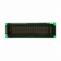
... M0220MD‐202MDAR1‐3 Dot‐matrix Character Vacuum Fluorescent Display Module M‐ VFD Module 0220‐ 2 lines x 20 characters M‐ Model D‐ Dot‐Matrix ...
Page 2
Document Revision History Revision Date 0 3/21/2005 1 9/21/2009 2 12/4/2009 Reduce pixel size to increase brightness and lifetime Functions and Features • 2 lines x 20 characters • Built‐in controller • Built‐in VF AC power supply • 5.0V power supply • 5x8 dots with cursor • Parallel interface (Serial interface selectable by jumpers) ...
Page 3
Mechanical Drawing ...
Page 4
Pattern Detail ...
Page 5
Pin Description (parallel interface) Pin No. Symbol External Connection 1 VSS Power Supply 2 VDD Power Supply 3 NC (/RST) ‐ 4 RS MPU 5 R/W MPU 6 E MPU 7‐10 DB0 – DB3 MPU 11‐14 DB4 – DB7 MPU Recommended LCD connector: 2.54mm pitch pins Pin Description (optional serial interface) Pin No. Symbol External Connection 1 ...
Page 6
Block Diagram ...
Page 7
Electrical Characteristics Item Operating Temperature Range Storage Temperature Range Operating Humidity Storage Humidity Vibration Shock Supply Voltage Supply Current (*Note) Luminance “H” Level input “L” Level input “H” Level output “L” Level output *Note: In-rush current can be approx 10 ...
Page 8
Table of Commands ...
Page 9
M68 Parallel Interface: The PT6314 can interface with the CPU in 4‐bits or 8‐bits. Note that the internal registers are composed of 8 bits. During data transfer in 4‐bit mode, DB4‐DB7 performs the data transfer operation two times, DB0‐DB3 should be tied HIGH or LOW. 4‐bit Data Transfer (M68): ...
Page 10
8‐bit Data Transfer (M68): ...
Page 11
Built‐in Font Table ...
Page 12
Example Initialization after Power ON ...
Page 13
Quality Information Test Item High Temperature storage storage temperature for a long time. Low Temperature storage Endurance test applying the low storage temperature for a long time. High Temperature Endurance test applying the electric stress Operation (voltage & current) and the high thermal stress for a long time. Low Temperature Endurance test applying the electric stress Operation (voltage & current) and the low thermal stress for a long time. High Temperature / Endurance test applying the electric stress Humidity Operation (voltage & current) and the high thermal with high humidity stress for a long time. Thermal Shock resistance Endurance test applying the electric stress (voltage & current) during a cycle of low and high thermal stress. Vibration test Endurance test applying vibration to simulate transportation and use. Static electricity test Endurance test applying electric static discharge. Note 1: No condensation to be observed. Note 2: Conducted after 4 hours of storage at 25 Note 3: Test performed on product itself, not inside a container. ...