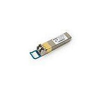
AFCT-57R5ATPZ Avago Technologies US Inc., AFCT-57R5ATPZ Datasheet

AFCT-57R5ATPZ
Specifications of AFCT-57R5ATPZ
Available stocks
Related parts for AFCT-57R5ATPZ
AFCT-57R5ATPZ Summary of contents
Page 1
... AFCT-57R5ATPZ SFP, 1310 nm, 10 km, LC Connector, Pluggable Fibre Channel 4.25/2.125/1.0625 GBd Data Sheet 1310 nm, 10 km, SFP (Small Form Pluggable), Low Voltage (3.3 V) Digital Diagnostic Optical Transceiver Description Installation Features • Diagnostic features per SFF-8472 “Diagnostic Monitoring Interface for Optical Transceivers” ...
Page 2
Digital Diagnostic Interface and Serial Identification Predictive Failure Identification 2 Compliance Prediction Fault Isolation Component Monitoring ...
Page 3
OPTICAL INTERFACE RECEIVER LIGHT FROM FIBER TRANSMITTER LIGHT TO FIBER Figure 1. Transceiver functional diagram. Transmitter Section Transmit Disable (TX_DISABLE) 3 AMPLIFICATION PHOTO-DETECTOR & QUANTIZATION CONTROLLER & MEMORY LASER DRIVER & VCSEL SAFETY CIRCUITRY Transmit Fault (TX_FAULT) ELECTRICAL INTERFACE RD+ ...
Page 4
Receiver Section Receiver Loss of Signal (Rx_LOS) Functional Data I/O 4 Application Support Caution Ordering Information www.avagotech.com www.sffcommittee.org Regulatory Compliance Electrostatic Discharge (ESD) ...
Page 5
Table 1. Regulatory Compliance Feature Test Method Electrostatic Discharge (ESD) MIL-STD-883C to the Electrical Pins Method 3015.4 Electrostatic Discharge (ESD) Variation of IEC 61000-4-2 to the Duplex LC Receptacle GR1089 Electrostatic Discharge (ESD) Variation of IEC 801-2 to the Optical ...
Page 6
Tx_DISABLE Tx_FAULT SERDES IC PROTOCOL IC LOSS OF SIGNAL 4 MODULE DETECT SCL SDA Figure 2. Typical application configuration 0 0 SFP MODULE HOST BOARD NOTE: ...
Page 7
Table 2. Pin Description Pin Name Function/Description 1 VeeT Transmitter Ground 2 TX_FAULT Transmitter Fault Indication – High indicates a fault condition 3 TX_DISABLE Transmitter Disable – Module optical output disables on high or open 4 MOD-DEF2 Module Definition 2 ...
Page 8
Table 3. Absolute Maximum Ratings Parameter Storage Temperature Case Operating Temperature Relative Humidity Supply Voltage Low Speed Input Voltage Notes; 1. Absolute Maximum Ratings are those values beyond which damage to the device may occur if these limits are exceeded ...
Page 9
Table 6. Transmitter and Receiver Electrical Characteristics ( VccT, VccR = 3 Parameter High Speed Data Input: Transmitter Differential Input Voltage (TD +/-) High Speed Data Output: Receiver Differential Output Voltage (RD ...
Page 10
Table 7. Transmitter Optical Characteristics ( VccT, VccR = 3 Parameter Modulated Optical Output Power (OMA) (Peak-to-Peak) 4.25 Gb/s Modulated Optical Output Power (OMA) (Peak-to-Peak) 2.125 Gb/s Modulated Optical Output Power (OMA) ...
Page 11
Table 8. Receiver Optical Characteristics ( VccT, VccR = 3 Parameter Input Optical Power [Overdrive] Input Optical Modulation Amplitude (Peak-to-Peak) 4.25 Gb/s [Sensitivity] Input Optical Modulation Amplitude (Peak-to-Peak) 2.125 Gb/s [Sensitivity] Input ...
Page 12
Table 9. Transceiver Timing Characteristics ( VccT, VccR = 3 Parameter Hardware TX_DISABLE Assert Time Hardware TX_DISABLE Negate Time Time to initialize, including reset of TX_FAULT Hardware TX_FAULT Assert Time Hardware TX_DISABLE ...
Page 13
Table 10. Transceiver Digital Diagnostic Monitor (Real Time Sense) Characteristics ( VccT, VccR = 3 Parameter Transceiver Internal Temperature Accuracy Transceiver Internal Supply Voltage Accuracy Transmitter Laser DC Bias Current Accuracy Transmitted ...
Page 14
V T,R > 2. TX_FAULT TX_DISABLE TRANSMITTED SIGNAL t_init t-init: TX DISABLE NEGATED V T,R > 2. TX_FAULT TX_DISABLE TRANSMITTED SIGNAL t_init INSERTION t-init: TX DISABLE NEGATED, MODULE HOT PLUGGED OCCURANCE OF FAULT TX_FAULT TX_DISABLE TRANSMITTED ...
Page 15
... Addresses 63 and 95 are checksums calculated (per SFF-8472 and SFF-8074) and stored prior to product shipment. 5. Addresses 68-83 specify the AFCT-57R5ATPZ ASCII serial number and will vary on a per unit basis. 6. Addresses 84-91 specify the AFCT-57R5ATPZ ASCII date code and will vary on a per date code basis. 15 ...
Page 16
... Transmitted average optical power (Tx Pwr) is decoded bit unsigned integer in increments of 0 Received average optical power (Rx Pwr) is decoded bit unsigned integer in increments of 0 Bytes 55-94 are not intended for use with AFCT-57R5ATPZ, but have been set to default values per SFF-8472. 7. Byte checksum calculated (per SFF-8472) and stored prior to product shipment. ...
Page 17
... Indicates transceiver is powered and real time sense data is ready Ready) Notes: 1. The response time for soft commands of the AFCT-57R5ATPZ is 100 msec as specified by the MSA SFF-8472. 2. Bit 6 is logic OR’d with the SFP TX_DISABLE input pin 3 ... either asserted will disable the SFP transmitter. ...
Page 18
Figure 5. Module drawing. 18 850 nm ...
Page 19
X Y 16.25 MIN. PITCH B PCB EDGE 5.68 8.58 11.08 16.25 REF. 14.25 2.0 11x 3 3.2 PIN 1 10.93 9.6 0.8 TYP 1.55 0.05 0 DETAIL 1 Figure 6. SFP ...
Page 20
MAX. 11.73 REF 9.8 MAX. PCB Figure 7. SFP assembly drawing. For product information and a complete list of distributors, please go to our website: Avago, Avago Technologies, and the A logo are trademarks of ...


