HFBR-1527Z Avago Technologies US Inc., HFBR-1527Z Datasheet - Page 10
HFBR-1527Z
Manufacturer Part Number
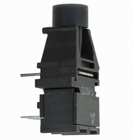
HFBR-1527Z
Description
FIBER OPTIC TX 125 MBD 650N
Manufacturer
Avago Technologies US Inc.
Specifications of HFBR-1527Z
Wavelength
650nm
Spectral Bandwidth
21nm
Voltage - Forward (vf) Typ
2.1V
Current - Dc Forward (if)
60mA
Voltage - Dc Reverse (vr) (max)
3V
Capacitance
60pF
Connector Type
Versatile Link
Function
Ideal for solving problems with voltage isolation/insulation, EMI/RFI immunity or data security.
Product
Transmitter
Data Rate
1 MBd, 125 MBd
Diode Capacitance
60 pF
Maximum Rise Time
12 ns (Typ)
Maximum Fall Time
9 ns (Typ)
Operating Supply Voltage
5.25 VDC
Maximum Operating Temperature
+ 70 C
Minimum Operating Temperature
0 C
Data Rate Max
1Mbps
Forward Current If
80mA
Forward Voltage
1.67V
Reverse Voltage Vr
5V
Data Transmission Distance
50ft
Wavelength Typ
660nm
Msl
MSL 4 - 72 Hours
Fiber Material
Plastic
Rohs Compliant
Yes
Lead Free Status / RoHS Status
Lead free / RoHS Compliant
For Use With
Plastic Optical Fiber, Hard Clad Silica
Lead Free Status / RoHS Status
Lead free / RoHS Compliant, Lead free / RoHS Compliant
Other names
516-1746
HFBR-1527Z
Q2636587
HFBR-1527Z
Q2636587
Available stocks
Company
Part Number
Manufacturer
Quantity
Price
Company:

Part Number:
HFBR-1527Z
Manufacturer:
AVAGO
Quantity:
1 400


10
Notes:
1. For I
2. The propagation delay for one meter of cable is typically 5 ns.
3. Estimated typical link life expectancy at 40°C exceeds 10 years at 60 mA.
4. Pulsed LED operation at I
1 MBd Link
(High Performance HFBR-15X2Z/25X2Z, Standard HFBR-15X4Z/25X4Z)
System Performance Under recommended operating conditions unless otherwise specified.
Performance
1 MBd
High
Standard
1 MBd
pulse width distortion of the receiver output signal.
I
I
FPK
FPK
FPK
≤160 mA: Pulse width ≤1 ms
> 160 mA: Pulse width ≤1 μS, period ≥20 μS.
> 80 mA, the duty factor must be such as to keep I
Data Rate
Link Distance
(Standard Cable)
Link Distance
(Improved Cable)
Propagation
Delay
Pulse Width
Distortion t
Data Rate
Link Distance
(Standard Cable)
Link Distance
(Improved Cable)
Propagation
Delay
Pulse Width
Distortion t
Parameter
Parameter
FPK
> 80 mA will cause increased link t
PLH
PLH
-t
-t
PHL
PHL
Symbol
Symbol
t
t
t
t
PLH
PHL
PLH
PHL
t
t
D
D
Fdc
Min.
Min.
dc
39
47
45
56
dc
17
10
19
8
≤80 mA. In addition, for I
PLH
propagation delay time. This extended t
Typ.
180
100
Typ.
180
100
70
78
80
43
48
80
Max.
Max.
250
140
250
140
1
1
Units
Units
MBd
MBd
FPK
ns
ns
ns
ns
ns
ns
m
m
m
m
m
m
m
m
> 80 mA, the following rules for pulse width apply:
BER ≤10
I
I
I
I
R
I = 0.5 metre
P
P
R
BER ≤10
I
I
I
I
R
I = 0.5 metre
P
P
R
Fdc
Fdc
Fdc
Fdc
Fdc
Fdc
Fdc
Fdc
L
R
R
L
L
R
R
L
= 560 Ω, C
= 560 Ω, C
= 560 Ω, C
= 560 Ω, C
= -24 dBm
= -24 dBm
= -20 dBm
= -20 dBm
= 60 mA
= 60 mA, 25°C
= 60 mA
= 60 mA, 25°C
= 60 mA
= 60 mA, 25°C
= 60 mA
= 60 mA, 25°C
Conditions
Conditions
-9
-9
, PRBS:2
, PRBS:2
L
L
L
L
PLH
= 30 pF
= 30 pF
= 30 pF
= 30 pF
time contributes to increased
7
7
-1
-1
Fig. 16, 18
Fig. 16, 17
Fig. 16, 18
Notes 2, 4
Fig. 16, 17
Notes 2, 4
Notes 1,
Notes 1,
Notes 1,
Notes 1,
Fig. 14
Fig. 15
Note 4
Fig. 12
Fig. 13
Note 4
Ref.
Ref.
3, 4
3, 4
3, 4
3, 4
Related parts for HFBR-1527Z
Image
Part Number
Description
Manufacturer
Datasheet
Request
R

Part Number:
Description:
XMITTER FIBER OPTIC SERCOS SMA
Manufacturer:
Avago Technologies US Inc.
Datasheet:

Part Number:
Description:
FIBER OPTIC CBL SIMPLEX 1=100M
Manufacturer:
Avago Technologies US Inc.
Datasheet:

Part Number:
Description:
FIBER OPTIC CBL SIMPLEX 1=500M
Manufacturer:
Avago Technologies US Inc.
Datasheet:

Part Number:
Description:
FIBER OPTIC CONN LATCH GRY SIMPL
Manufacturer:
Avago Technologies US Inc.
Datasheet:

Part Number:
Description:
FIBER OPTIC CONN LATCH BLU SIMPL
Manufacturer:
Avago Technologies US Inc.
Datasheet:

Part Number:
Description:
XMITTER VERSATILE LINK HORZ
Manufacturer:
Avago Technologies US Inc.
Datasheet:

Part Number:
Description:
Fiber Optic Transmitters, Receivers, Transceivers 1300nm 155MBd 16-pin DIP ST Rx
Manufacturer:
Avago Technologies US Inc.

Part Number:
Description:
FIBER OPTIC CBL DUPLEX 1=100M
Manufacturer:
Avago Technologies US Inc.
Datasheet:
Part Number:
Description:
FIBER OPTIC CBL SIMPLEX 1=500M
Manufacturer:
Avago Technologies US Inc.
Datasheet:
Part Number:
Description:
FIBER OPTIC CBL DUPLEX 1=500M
Manufacturer:
Avago Technologies US Inc.
Datasheet:

Part Number:
Description:
OPTOCOUPLER GATE DRV 2A 16-SOIC
Manufacturer:
Avago Technologies US Inc.
Datasheet:
Part Number:
Description:
OPTOCOUPLER 2CH 2.5A 16-SOIC
Manufacturer:
Avago Technologies US Inc.
Datasheet:

Part Number:
Description:
OPTOCOUPLER GATE DRV 0.4A 16SOIC
Manufacturer:
Avago Technologies US Inc.
Datasheet:

Part Number:
Description:
OPTOCOUPLER 2.0A 250KHZ 8-DIP
Manufacturer:
Avago Technologies US Inc.
Datasheet:

Part Number:
Description:
OPTOCOUPLER 2.0A 250KHZ GW 8-SMD
Manufacturer:
Avago Technologies US Inc.
Datasheet: