B32521C6223J EPCOS Inc, B32521C6223J Datasheet - Page 38
B32521C6223J
Manufacturer Part Number
B32521C6223J
Description
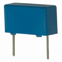
CAP .022UF 400V METAL POLY
Manufacturer
EPCOS Inc
Series
MKT B32521r
Datasheet
1.B32520C1104J.pdf
(46 pages)
Specifications of B32521C6223J
Capacitance
0.022µF
Voltage - Ac
200V
Voltage - Dc
400V
Dielectric Material
Polyester, Metallized
Tolerance
±5%
Operating Temperature
-55°C ~ 125°C
Mounting Type
Through Hole
Package / Case
Radial
Size / Dimension
0.512" L x 0.158" W (13.00mm x 4.00mm)
Height
0.276" (7.00mm)
Termination
PC Pins
Lead Spacing
0.394" (10.00mm)
Features
General Purpose
Capacitor Dielectric Type
Polyester
Capacitance Tolerance
± 5%
Voltage Rating
400VDC
Life Time @ Temperature
200000 Hours @ 40°C
Termination Style
Radial
Product
Metallized Polyester Film Capacitors
Lead Free Status / RoHS Status
Lead free / RoHS Compliant
Esr (equivalent Series Resistance)
-
Lead Free Status / Rohs Status
Details
Other names
495-1230
B32521C6223J000
B32521C6223J000


1.3
Permissible heat exposure loads on film capacitors are primarily characterized by the upper cate-
gory temperature T
can lead to changes in the plastic dielectric and thus change irreversibly a capacitor's electrical
characteristics. For short exposures (as in practical soldering processes) the heat load (and thus
the possible effects on a capacitor) will also depend on other factors like:
The overheating associated with some of these factors can usually be reduced by suitable coun-
termeasures. For example, if a pre-heating step cannot be avoided, an additional or reinforced
cooling process may possibly have to be included.
EPCOS recommends the following conditions:
Uncoated capacitors
For uncoated MKT capacitors with lead spacings 10 mm (B32560/B32561) the following mea-
sures are recommended:
Please read Important notes
at the end of this document.
Pre-heating temperature and time
Forced cooling immediately after soldering
Terminal characteristics:
diameter, length, thermal resistance, special configurations (e.g. crimping)
Height of capacitor above solder bath
Shadowing by neighboring components
Additional heating due to heat dissipation by neighboring components
Use of solder-resist coatings
Pre-heating with a maximum temperature of 110 C
Temperature inside the capacitor should not exceed the following limits:
When SMD components are used together with leaded ones, the leaded film capacitors should
not pass into the SMD adhesive curing oven. The leaded components should be assembled af-
ter the SMD curing step.
Leaded film capacitors are not suitable for reflow soldering.
pre-heating to not more than 110 C in the preheater phase
rapid cooling after soldering
MKP/MFP 110 C
MKT 160 C
General notes on soldering
B32520 ... B32529
General purpose (stacked/wound)
max
. Long exposure to temperatures above this type-related temperature limit
Page 38 of 46
Related parts for B32521C6223J
Image
Part Number
Description
Manufacturer
Datasheet
Request
R


Part Number:
Description:
CAP .15UF 63V METAL POLY
Manufacturer:
EPCOS Inc
Datasheet:


Part Number:
Description:
CAP .01UF 400V METAL POLY
Manufacturer:
EPCOS Inc
Datasheet:
