HSMR-C150 Avago Technologies US Inc., HSMR-C150 Datasheet
HSMR-C150
Specifications of HSMR-C150
Available stocks


Related parts for HSMR-C150


HSMR-C150 Summary of contents
Page 1
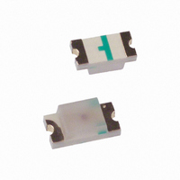
... HSMQ-C1xx and HSMR-C1xx High Performance Chip LED Data Sheet HSMQ-C110, HSMQ-C120, HSMQ-C150, HSMQ-C170, HSMQ-C177, HSMQ-C190, HSMQ-C191, HSMQ-C197, HSMQ-C265, HSMR-C110, HSMR-C120, HSMR-C130, HSMR-C150, HSMR-C170, HSMR-C177, HSMR-C190, HSMR-C191, HSMR-C197, HSMR-C265 Description These small chip-type LEDs utilize high efficient and high brightness InGaN material to deliver competitively priced high performance blue and green. These 520 nm green and 470 nm blue are unique hues which provide color differentiation to a product ...
Page 2
Package Dimensions LED DIE 2.6 (0.102 ) 3.2 (0.126 ) CLEAR EPOXY PC BOARD 1.6 (0.063 ) 3.2 (0.126 ) 0.8 (0.031) CATHODE LINE SOLDERING TERMINAL HSMx-C110 CATHODE MARK 1.6 (0.063 ) 1.0 (0.039) 0.3 (0.012) DIFFUSED EPOXY PC BOARD ...
Page 3
Package Dimensions, continued 3.2 (0.126 ) DIFFUSED 2.0 (0.079) EPOXY 0.6 (0.024) PC BOARD CATHODE LINE 0.5 (0.020) 0.50 ± 0.20 (0.020 ± 0.008) SOLDERING TERMINAL HSMx-C150 CATHODE MARK 0.80 1.60 (0.031) (0.063) DIFFUSED EPOXY PC BOARD 0.16 (0.006) CATHODE ...
Page 4
... PCB BOARD CATHODE LINE 0.3 ± 0.15 0.50 ± 0.15 (0.012 ± 0.006) (0.020 ± 0.006) InGaN Green InGaN Blue HSMQ-C110 HSMR-C110 HSMQ-C120 HSMR-C120 – HSMR-C130 HSMQ-C150 HSMR-C150 HSMQ-C170 HSMR-C170 HSMQ-C177 HSMR-C177 HSMQ-C190 HSMR-C190 HSMQ-C191 HSMR-C191 HSMQ-C197 HSMR-C197 HSMQ-C265 HSMR-C265 HSMQ-Cxxx HSMR-Cxxx ...
Page 5
... Part Number Color HSMQ-C110 Green HSMQ-C120 Green HSMQ-C150/170/190/191 Green HSMQ-C177/197 Green HSMQ-C265 Green HSMR-C110 Blue HSMR-C120 Blue HSMR-C130 Blue HSMR-C150/170/190/191 Blue HSMR-C177/197 Blue HSMR-C265 Blue Notes: 1. The luminous intensity measured at the peak of the spatial radiation pattern which may not be aligned with the mechanical axis of the lamp V package. 2. The dominant wavelength, λ derived from the CIE Chromaticity Diagram and represents the perceived color of the device θ is the off-axis angle where the luminous intensity is 1/2 the peak intensity. 1/2 ...
Page 6
Light Intensity (Iv) Bin Limits Intensity (mcd) Bin ID Min. Max. A 0.11 0.18 B 0.18 0.29 C 0.29 0.45 D 0.45 0.72 E 0.72 1.10 F 1.10 1.80 G 1.80 2.80 H 2.80 4.50 J 4.50 7.20 K ...
Page 7
ANGLE 100 -90 -70 -50 -30 -10 ANGLE Figure 5. Relative intensity vs. angle for HSMx-C110. 100 ...
Page 8
ANGLE Figure 7. Relative intensity vs. angle for HSMx-C177 and C197. 100 ...
Page 9
SEC. MAX. 230°C MAX. 4°C/SEC. MAX. 140-160°C 4°C/SEC. MAX. OVER 2 MIN. TIME Figure 11. Recommended reflow soldering profile. 5.0 (0.200) 0.9 (0.035) 0.9 (0.035) 0.2 (0.008) 1.5 2.0 1.5 (0.059) (0.079) (0.059) Figure 13. Recommended soldering pattern for ...
Page 10
USER FEED DIRECTION PRINTED LABEL Figure 19. Reeling orientation. 3.0 ± 0.5 (0.118 ± 0.020) 178.40 ± 1.00 (7.024 ± 0.039) 4.0 ± 0.5 (0.157 ± 0.020) Figure 20. Reel dimensions. NOTE: 1. ALL DIMENSIONS IN MILLIMETERS (INCHES). 10 CATHODE ...
Page 11
... HSMx-C265 SERIES 3.70 (0.146) 1.45 (0.057) 0.20 ± 0.05 0.23 ± 0.05 (0.008 ± 0.002) (0.009 ± 0.002) FOR HSMR-C130 CARRIER TAPE COVER TAPE DIM. C ± 0.10 (0.004) 1.20 (0.047) 0.75 (0.030) 1.27 (0.050) 0.95 (0.037) ...
Page 12
END THERE SHALL BE A MOUNTED WITH MINIMUM OF 160 mm COMPONENTS (6.3 INCH) OF EMPTY COMPONENT POCKETS SEALED WITH COVER TAPE. Figure 22. Tape leader and trailer dimensions. NOTES: 1. ALL DIMENSIONS IN MILLIMETERS (INCHES). 2. TOLERANCE IS ± ...