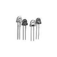
HLMP-3316-I0002 Avago Technologies US Inc., HLMP-3316-I0002 Datasheet

HLMP-3316-I0002
Specifications of HLMP-3316-I0002
Available stocks
Related parts for HLMP-3316-I0002
HLMP-3316-I0002 Summary of contents
Page 1
... The light generated is focused to a narrow beam to achieve this effect. Luminous Intensity Iv (mcd Min. Max. 13.8 22.00 22.0 22.0 70.4 9.2 14.7 14.7 37.6 120.2 6.7 10.6 10.6 43.6 139.6 HLMP-331x Series HLMP-341x Series HLMP-351x Series - - - - - - - - - ...
Page 2
... Package Dimensions Part Numbering System HLMP - Mechanical Option 00: Bulk 01: Tape & Reel, Crimped Leads 02: Tape & Reel, Straight Leads B1: Right Angle Housing, Uneven Leads B2: Right Angle Housing, Even Leads Color Bin Options 0: Full Color Bin Distribution Maximum Iv Bin Options 0: Open (no max. limit) ...
Page 3
... CIE chromaticity diagram and represents the single wavelength which defines the d color of the device. 3. Radiant intensity watts/steradian, may be found from the equation the luminous efficacy in lumens/watt Device HLMP- Min. Typ. Max. 3315 13.8 40.0 3316 22 60.0 3415 9 ...
Page 4
Absolute Maximum Ratings at T Parameter Peak Forward Current [1] Average Forward Current DC Current [2] [3] Power Dissipation Reverse Voltage (I = 100 A) R Transient Forward Current [4] (10 sec Pulse) LED Junction Temperature Operating Temperature Range Storage ...
Page 5
... High Efficiency Red HLMP-331X Series Figure 2. Forward Current vs. Forward Voltage Characteristics. Figure 5. Maximum Tolerable Peak Current vs. Pulse Duration (I MAX DC as per MAX Ratings). Figure 3. Relative Luminous Intensity vs. DC Forward Current. Figure 6. Relative Luminous Intensity vs. Angular Displacement. 5 Figure 4. Relative Efficiency (Luminous Intensity per Unit Current) ...
Page 6
... Yellow HLMP-341X Series Figure 7. Forward Current vs. Forward Voltage Characteristics. Figure 10. Maximum Tolerable Peak Current vs. Pulse Duration (I MAX DC as per MAX Ratings). Figure 8. Relative Luminous Intensity vs. DC Forward Current. Figure 11. Relative Luminous Intensity vs. Angular Displacement. 6 Figure 9. Relative Efficiency (Luminous Intensity per Unit Current) ...
Page 7
... Green HLMP-351X Series Figure 12. Forward Current vs. Forward Voltage Characteristics. Figure 15. Maximum Tolerable Peak Current vs. Pulse Duration (I MAX DC as per MAX Ratings). Figure 13. Relative Luminous Intensity vs. DC Forward Current. Figure 16. Relative Luminous Intensity vs. Angular Displacement. T-1 Lamp. 7 Figure 14. Relative Efficiency (Luminous Intensity per Unit Current) vs ...
Page 8
Table 2. Intensity Bin Limit Intensity Range (mcd) Color Bin Min. Max. H 15.5 24.8 I 24.8 39.6 J 39.6 63.4 K 63.4 101.5 L 101.5 162.4 M 162.4 234.6 N 234.6 340.0 O 340.0 540.0 Red P 540.0 850.0 ...
Page 9
Color Categories Color Cat # 6 5 Green Yellow Tolerance for each bin limit is 0.5 nm. Mechanical Option Matrix Mechanical Option Code Note: All Categories are ...
Page 10
Data subject to change. Copyright © 2001 Agilent Technologies, Inc. July 16, 2001 Obsoletes 5964-9293E (4/96) 5988-2146EN ...


