HLMP-3554-E0002 Avago Technologies US Inc., HLMP-3554-E0002 Datasheet - Page 7
HLMP-3554-E0002
Manufacturer Part Number
HLMP-3554-E0002
Description
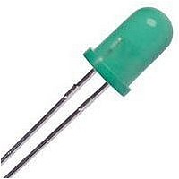
LED 5MM GAP GRN LOPRO CRIMP LDS
Manufacturer
Avago Technologies US Inc.
Datasheet
1.HLMP-3351.pdf
(9 pages)
Specifications of HLMP-3554-E0002
Viewing Angle
50°
Color
Green
Millicandela Rating
6.7mcd
Current - Test
10mA
Wavelength - Dominant
569nm
Wavelength - Peak
565nm
Voltage - Forward (vf) Typ
2.1V
Lens Type
Diffused, Green Tinted
Lens Style/size
Round, 5mm, T-1 3/4
Package / Case
Radial - 2 Lead
Height
5.84mm
Mounting Type
Through Hole
Resistance Tolerance
569nm
Bulb Size
T-1 3/4 (5mm)
Led Color
Green
Luminous Intensity
6.7mcd
Forward Current If
10mA
Forward Voltage
2.1V
Led Mounting
Through Hole
Lens Shape
Round
Lead Free Status / RoHS Status
Contains lead / RoHS non-compliant
Luminous Flux @ Current - Test
-
Lead Free Status / RoHS Status
Lead free / RoHS Compliant, Contains lead / RoHS non-compliant
Available stocks
Company
Part Number
Manufacturer
Quantity
Price
Company:

Part Number:
HLMP-3554-E0002
Manufacturer:
AVAGO
Quantity:
50 000


Green HLMP-355x/-356x Series
Electrical Specifications at T
Notes:
1. q
2. Dominant wavelength, λ
3. Radiant Intensity, I
Figure 17. Forward current vs. forward voltage.
7
Symbol
2q
λ
λ
Δλ
τ
C
Rq
V
V
η
s
PEAK
d
F
R
V
1/2
J-PIN
device.
luminous efficacy in lumens/watt.
1/2
1
/
2
is the off-axis angle at which the luminous intensity is half the axial luminous intensity.
Description
Including Angle Between
Half Luminous Intensity
Points
Peak Wavelength
Dominant Wavelength
Spectral Line Halfwidth
Speed of Response
Capacitance
Thermal Resistance
Forward Voltage
Reverse Breakdown Voltage
Luminous Efficacy
e
, in watts/steradian may be found from the equation I
d
, is derived from the CIE chromaticity diagram and represents the single wavelength which defines the color of the
A
= 25°C
Figure 18. Relative luminous intensity vs.
forward current.
Device
HLMP-
3554
3568
Min.
5.0
e
= I
v
/η
Typ.
50
40
565
569
28
500
18
260
2.1
595
v
, where I
v
is the luminous intensity in candelas and η
Max.
2.7
Figure 19. Relative efficiency (luminous intensity
per unit current) vs. peak current.
Units
Deg.
nm
nm
nm
ns
pF
°C/W
V
V
lm/W
Test Conditions
Note 1
(Figure 21)
Measurement at
Peak (Figure 1)
Note 2
V
Junction to
Cathode Lead
I
(Figure 17)
I
Note 3
F
R
F
= 10 mA
= 100 μA
= 0; f = 1 MHz
v
is the
Related parts for HLMP-3554-E0002
Image
Part Number
Description
Manufacturer
Datasheet
Request
R

Part Number:
Description:
LED 5MM 565NM GREEN DIFF LO PRO
Manufacturer:
Avago Technologies US Inc.
Datasheet:

Part Number:
Description:
LED 5MM GAP GREEN LOW PROFILE
Manufacturer:
Avago Technologies US Inc.
Datasheet:

Part Number:
Description:
LED 5MM 639NM RED WATER CLEAR
Manufacturer:
Avago Technologies US Inc.
Datasheet:

Part Number:
Description:
LED 5MM 635NM HE RED WATER CLEAR
Manufacturer:
Avago Technologies US Inc.
Datasheet:

Part Number:
Description:
LED 3MM 569NM GREEN DIFF
Manufacturer:
Avago Technologies US Inc.
Datasheet:

Part Number:
Description:
LED LT BAR 19.05X3.81MM SGL YLW
Manufacturer:
Avago Technologies US Inc.
Datasheet:

Part Number:
Description:
LED Lamp
Manufacturer:
Avago Technologies US Inc.
Datasheet:

Part Number:
Description:
LED 5MM ALINGAP 590NM AMB 15DEG
Manufacturer:
Avago Technologies US Inc.
Datasheet:

Part Number:
Description:
LED T1 3/4 5MM WHT PREC OPT PREF
Manufacturer:
Avago Technologies US Inc.
Datasheet:

Part Number:
Description:
LED 5MM FLAT TOP INGAN WHITE
Manufacturer:
Avago Technologies US Inc.
Datasheet:
Part Number:
Description:
LED 5MM FLAT TOP INGAN WHITE
Manufacturer:
Avago Technologies US Inc.
Datasheet:
Part Number:
Description:
LED 5MM FLAT TOP INGAN WHITE
Manufacturer:
Avago Technologies US Inc.
Datasheet:
Part Number:
Description:
LED 5MM FLAT TOP INGAN WHITE
Manufacturer:
Avago Technologies US Inc.
Datasheet:

Part Number:
Description:
LED T 1 3/4 OR 5MM AMBER
Manufacturer:
Avago Technologies US Inc.
Datasheet:

Part Number:
Description:
LED T1-3/4 SUPER BRIGHT GREEN
Manufacturer:
Avago Technologies US Inc.