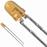
HLMP-1421-F00A2 Avago Technologies US Inc., HLMP-1421-F00A2 Datasheet

HLMP-1421-F00A2
Specifications of HLMP-1421-F00A2
Available stocks
Related parts for HLMP-1421-F00A2
HLMP-1421-F00A2 Summary of contents
Page 1
... HLMP-152x Series T-1 (3 mm) High Intensity LED Lamps Data Sheet Description This family of T-1 lamps is specially designed for applica- tions requiring higher on-axis intensity than is achievable with a standard lamp. The light generated is focused to a narrow beam to achieve this effect. Package Dimensions Features • High intensity • Choice of 3 bright colors High Efficiency Red Yellow High Performance Green • Popular T-1 diameter package • Selected minimum intensities • Narrow viewing angle • General purpose leads • ...
Page 2
Part Numbering System Mechanical Option 00: Bulk 01: Tape & Reel, Crimped Leads 02: Tape & Reel, Straight Leads A1: Right Angle Housing, Uneven Leads A2: Right Angle Housing, Even Leads Color Bin Options 0: Full Color Bin Distribution Maximum Iv Bin Options 0: Open (no max. limit) Others: Please refer to the Iv Bin Table Minimum Iv Bin Options Please refer to the Iv Bin Table ...
Page 3
... J-PIN V Forward Voltage F V Reverse Breakdown Voltage R h Luminous Efficacy V Notes the off-axis angle at which the luminous intensity is half the axial luminous intensity The dominant wavelength derived from the CIE chromaticity diagram and represents the single wavelength which defines the color of d the device. 3. Radiant intensity watts/steradian, may be found from the equation I e luminous efficacy in lumens/watt. 3 Device HLMP- Min. Typ. Max. 1320 8.6 30 1321 8.6 30 1420 9.2 15 1421 9.2 15 1520 6.7 22 1521 6.7 22 All 45 132x 635 ...
Page 4
Figure 1. Relative intensity vs. wavelength. T-1 High Efficiency Red Non-Diffused ...
Page 5
T-1 Yellow Non-Diffused 1.0 1.5 1.0 2.0 1.5 2.5 2.0 3.0 2.5 3.5 3.0 4.0 3.5 1.0 1.5 2.0 ...
Page 6
T-1 Green Non-Diffused 1.0 2.0 2.0 3.0 3.0 4.0 4.0 5.0 5.0 1.0 2.0 3.0 4.0 5.0 V – FORWARD ...
Page 7
Intensity Bin Limits Intensity Range (mcd) Color Bin Min. G 9.7 H 15.5 I 24.8 J 39.6 K 63.4 L 101.5 M 162.4 N 234.6 O 340.0 P 540.0 Red Q 850.0 R 1200.0 S 1700.0 T 2400.0 U 3400.0 ...
Page 8
Color Categories Color Category # 6 5 Green Yellow Maximum tolerance for each bin limit is ±0.5 nm. Mechanical Option Matrix Mechanical Option Code Note: All categories ...
Page 9
Precautions: Lead Forming • The leads of an LED lamp may be preformed or cut to length prior to insertion and soldering into PC board. • If lead forming is required before soldering, care must be taken to avoid any excessive mechanical stress induced to LED package. Otherwise, cut the leads of LED to length after soldering process at room temperature. The solder joint formed will absorb the mechanical stress of the lead cutting from traveling to the LED chip die attach and wirebond. • recommended that tooling made to precisely form and cut the leads to length rather than rely upon hand operation. ...


