HLMP-0800 Avago Technologies US Inc., HLMP-0800 Datasheet - Page 3
HLMP-0800
Manufacturer Part Number
HLMP-0800
Description
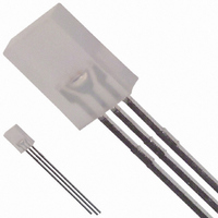
LED 2X5MM BICOLOR GREEN/HER DIFF
Manufacturer
Avago Technologies US Inc.
Datasheet
1.HLMP-4000.pdf
(7 pages)
Specifications of HLMP-0800
Viewing Angle
100°
Color
Green, Red
Millicandela Rating
2.6mcd Green, 2.1mcd Red
Current - Test
20mA
Wavelength - Dominant
570nm, 626nm
Wavelength - Peak
568nm, 635nm
Voltage - Forward (vf) Typ
2.2V Green, 1.9V Red
Lens Type
Diffused
Lens Style/size
Rectangle, 5mm x 2mm
Package / Case
Radial - 3 Lead
Height
8.00mm
Mounting Type
Through Hole
Resistance Tolerance
570nm, 626nm
Led Size
2 mm x 5 mm
Illumination Color
Green, High Efficiency Red
Lens Color/style
Diffused
Operating Voltage
2.2 V, 1.9 V
Wavelength
570 nm, 626 nm
Luminous Intensity
2.6 mcd, 2.1 mcd
Operating Current
20 mA
Lens Dimensions
2 mm x 5 mm
Lens Shape
Rectangular
Maximum Operating Temperature
+ 100 C
Minimum Operating Temperature
- 20 C
Mounting Style
Through Hole
Led Color
Red / Green
Luminous Intensity / Color
R 2.1mcd / G 2.6mcd
Forward Voltage / Color
R 1.9V / G 2.2V
Led Mounting
Through Hole
Rohs Compliant
Yes
Bulb Size
2mm X 5mm
Lead Free Status / RoHS Status
Lead free / RoHS Compliant
Luminous Flux @ Current - Test
-
Lead Free Status / Rohs Status
Lead free / RoHS Compliant
Other names
516-1280
Available stocks
Company
Part Number
Manufacturer
Quantity
Price
Company:

Part Number:
HLMP-0800
Manufacturer:
AVAGO
Quantity:
40 000
Company:
Part Number:
HLMP-0800
Manufacturer:
AVAGO
Quantity:
50 000


3
Absolute Maximum Ratings at T
Parameter
Peak Forward Current
Average Forward Current
DC Current
Power Dissipation
Operating Temperature Range
Storage Temperature Range
Reverse Voltage (I
Transient Forward Current
(10 sec Pulse)
Notes:
1. See Figure 5 to establish pulsed operating conditions.
2. The combined simultaneous current must not exceed the maximum.
3. The combined simultaneous current must not exceed the maximum.
4. The transient peak current is the maximum non-recurring current that can be applied to the device without damaging the LED die and wirebond. It is
Notes:
1. The dominant wavelength, l
2. q
3. Radiant intensity, le, in watts steradian, may be found from the equation le = Iv/h
Electrical/Optical Characteristics at T
Symbol Parameter
l
l
t
C
V
V
Rq
h
2q
s
PEAK
d
F
R
V
not recommended that the device be operated at peak currents beyond the peak forward current listed in the Absolute Maximum Ratings.
efficacy in lumens/watt.
J-PIN
1/2
1/2
is the off-axis angle at which the luminous intensity is half the axial luminous intensity.
Peak
Wavelength
Dominant
Wavelength
Speed of
Response
Capacitance
Forward
Voltage
Reverse
Voltage
Thermal
Resistance
Included Angle
between half
luminous
intensity points
Luminous
Efficacy
[2]
HLMP-40xx
HLMP-08xx
(Total)
[3]
[3]
R
= 100 A)
(Total)
[1]
d
[2]
[1,2]
, is derived from the CIE Chromaticity Diagram and represents the single wavelength which defines the color of the device.
[4]
High Efficiency Red
Min.
5
(Total)
A
= 25 C
Typ.
635
626
90
1.9
210
100
145
11
65
A
= 25˚C
Max.
2.6
HER/Green
135
–20 to +100
–55 to +100
5
500
90
25
30
Green
Min.
5
Typ.
568
570
260
18
2.2
210
65
100
595
V,
where Iv is the luminous intensity in candelas and h V is the luminous
Max.
3.0
Yellow/Green
60
20
20
135
–20 to +100
–55 to +100
5
500
Yellow
Min.
2.1
5
Typ.
210
100
583
585
90
15
2.6
65
500
Max. Units
nm
nm
ns
pF
V
V
degree
lm/W
C/W Junction-to-
Units
mA
mA
mA
mW
V
mA
C
C
Test Condition
20 mA
20 mA
V
20 mA
I
Cathode Lead
R
F
= 100 A
= 0, f = 1 MHz
Related parts for HLMP-0800
Image
Part Number
Description
Manufacturer
Datasheet
Request
R

Part Number:
Description:
LED 3MM 569NM GREEN DIFF
Manufacturer:
Avago Technologies US Inc.
Datasheet:

Part Number:
Description:
LED 5MM 635NM HE RED WATER CLEAR
Manufacturer:
Avago Technologies US Inc.
Datasheet:

Part Number:
Description:
LED 5MM 639NM RED WATER CLEAR
Manufacturer:
Avago Technologies US Inc.
Datasheet:

Part Number:
Description:
LED LT BAR 8.89X3.81MM SGL GREEN
Manufacturer:
Avago Technologies US Inc.
Datasheet:

Part Number:
Description:
LED LT BAR 19.05X3.81MM SGL YLW
Manufacturer:
Avago Technologies US Inc.
Datasheet:

Part Number:
Description:
LED Lamp
Manufacturer:
Avago Technologies US Inc.
Datasheet:

Part Number:
Description:
LED 5MM FLAT TOP INGAN WHITE
Manufacturer:
Avago Technologies US Inc.
Datasheet:
Part Number:
Description:
LED 5MM FLAT TOP INGAN WHITE
Manufacturer:
Avago Technologies US Inc.
Datasheet:
Part Number:
Description:
LED 5MM FLAT TOP INGAN WHITE
Manufacturer:
Avago Technologies US Inc.
Datasheet:
Part Number:
Description:
LED 5MM FLAT TOP INGAN WHITE
Manufacturer:
Avago Technologies US Inc.
Datasheet:

Part Number:
Description:
LED DOME 5V 635NM HER DFF RA AXL
Manufacturer:
Avago Technologies US Inc.
Datasheet:

Part Number:
Description:
LED DOME 5V 565NM GN DIFF RA AXL
Manufacturer:
Avago Technologies US Inc.
Datasheet:

Part Number:
Description:
LED DOME 583NM YLW DIFF RA AXIAL
Manufacturer:
Avago Technologies US Inc.
Datasheet:

Part Number:
Description:
LED 5MM GAP GRN RA HOUSING TH
Manufacturer:
Avago Technologies US Inc.
Datasheet:

Part Number:
Description:
LED 3MM GAP DIFF RED RA HOUSING
Manufacturer:
Avago Technologies US Inc.
Datasheet: