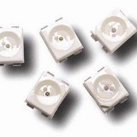
HSMS-A100-K30J2 Avago Technologies US Inc., HSMS-A100-K30J2 Datasheet - Page 8

HSMS-A100-K30J2
Manufacturer Part Number
HSMS-A100-K30J2
Description
LED IND 635NM RED TOP MT 2PLCC
Manufacturer
Avago Technologies US Inc.
Datasheet
1.HSMS-A100-J00J1.pdf
(12 pages)
Specifications of HSMS-A100-K30J2
Package / Case
2-PLCC
Viewing Angle
120°
Color
Red
Millicandela Rating
10.6mcd
Current - Test
20mA
Wavelength - Dominant
626nm
Wavelength - Peak
635nm
Voltage - Forward (vf) Typ
2.2V
Lens Type
Clear
Lens Style/size
Round, 2.2mm
Size / Dimension
3.20mm L x 2.80mm W
Height
1.90mm
Mounting Type
Surface Mount
Resistance Tolerance
626nm
Led Size
3.2 mm x 2.8 mm
Illumination Color
Red
Wavelength
626 nm
Mounting Style
SMD/SMT
Lead Free Status / RoHS Status
Lead free / RoHS Compliant
Luminous Flux @ Current - Test
-
Lead Free Status / RoHS Status
Lead free / RoHS Compliant, Lead free / RoHS Compliant
Figure 8. Recommended Pb-free reflow soldering profile.
Figure 6. Forward voltage shift vs. temperature.
Note: For detail information on reflow soldering of Avago surface
mount LEDs, do refer to Avago Application Note AN 1060 Surface
Mounting SMT LED Indicator Components.
Figure 9. Recommended wave soldering profile.
8
-0.1
-0.2
-0.3
250
200
150
100
0.5
0.4
0.3
0.2
0.1
50
30
0
-100
217 C
200 C
150 C
0
CONVEYOR SPEED = 1.83 M/MIN (6 FT/MIN)
PREHEAT SETTING = 150C (100C PCB)
SOLDER WAVE TEMPERATURE = 245C
AIR KNIFE AIR TEMPERATURE = 390C
AIR KNIFE DISTANCE = 1.91 mm (0.25 IN.)
AIR KNIFE ANGLE = 40
LEADED SOLDER: SN63; FLUX: RMA
LEAD-FREE SOLDER: 96.5 wt% SN, 3 wt% Ag, 0.5 wt% Cu
NOTE: ALLOW FOR BOARDS TO BE SUFFICIENTLY COOLED
BEFORE EXERTING MECHANICAL FORCE.
GaP/AlGaAs/
AlInGaP
10
-50
FLUXING
20
3 C/SEC. MAX.
PREHEAT
TEMPERATURE – °C
TURBULENT WAVE
3 C/SEC. MAX.
60 - 120 SEC.
255 - 260 C
30
0
InGaN/GaN
TIME – SECONDS
40
50
TIME
50
100
60
70
(Acc. to J-STD-020C)
LAMINAR WAVE
150
HOT AIR KNIFE
BOTTOM SIDE
OF PC BOARD
TOP SIDE OF
PC BOARD
100 SEC. MAX.
10 to 30 SEC.
80
6 C/SEC. MAX.
90
100
Figure 7. Radiation Pattern.
1.0
0.8
0.6
0.4
0.2
0
-90
-80
-70
Figure 10. Recommended soldering pad pattern.
2.60
-60
-50
-40
ANGULAR DISPLACEMENT – DEGREES
SOLDER RESIST
-30
-20
1.50
-10
0
10
4.50
20 30
40
50
60
70
80
90


