ASMT-QBBC-NAC0E Avago Technologies US Inc., ASMT-QBBC-NAC0E Datasheet

LED INDICATOR 0.5W BLUE 4PLCC

ASMT-QBBC-NAC0E

Manufacturer Part Number
ASMT-QBBC-NAC0E
Description
LED INDICATOR 0.5W BLUE 4PLCC
Manufacturer
Avago Technologies US Inc.
Datasheet

Specifications of ASMT-QBBC-NAC0E

Wavelength
464nm
Package / Case
PLCC-4 - 3.20mm L x 2.80mm W x 1.90mm H
Viewing Angle
120°
Color
Blue
Current - Test
150mA
Luminous Flux @ Current - Test
7lm
Current - Max
150mA
Lumens @ Current - Max
7lm
Lumens/watt @ Current - Test
14lm/W
Voltage - Forward (vf) Typ
3.4V
Lens Style/size
Round, 2.4mm
Mounting Type
Surface Mount
Led Size
3.2 mm x 2.8 mm
Illumination Color
Blue
Lens Color/style
Clear
Operating Voltage
3.4 V
Mounting Style
SMD/SMT
Operating Current
150 mA
Lens Dimensions
2.4 mm
Lens Shape
Flat Round
Peak Wavelength
458 nm
Lead Free Status / RoHS Status
Lead free / RoHS Compliant
Lead Free Status / RoHS Status
Lead free / RoHS Compliant, Lead free / RoHS Compliant

Available stocks

Company
Part Number
Manufacturer
Quantity
Price
Part Number:
ASMT-QBBC-NAC0E
Manufacturer:
AVAGO
Quantity:
50 000
ASMT-QxBC-Nxxxx
Super 0.5W Power PLCC-4
Surface Mount LED Indicator
Data Sheet
Description
The Super 0.5W Power PLCC-4 SMT LED is Blue mid-Power
PLCC-4 SMT LEDs using InGaN chip technology. The
package can be driven at high current due to its superior
package design. The product is able to dissipate the heat
more efficiently compared to the Power PLCC-4 SMT LEDs.
These LEDs produce higher light output with better flux
performance compared to the Power PLCC-4 SMT LED.
The Super 0.5W Power PLCC-4 SMT LEDs are designed for
higher reliability, better performance, and operate under
a wide range of environmental conditions. The perfor-
mance characteristics of these new mid-power LEDs make
them uniquely suitable for use in harsh conditions such as
in automotive applications, and in electronics signs and
signals.
To facilitate easy pick and place assembly, the LEDs are
packed in EIA-compliant tape and reel. Every reel is
shipped in single intensity and color bin, to provide close
uniformity.
CAUTION: ASMT-QxBC-Nxxxx LEDs are Class 2 ESD sensitive. Please observe appropriate precautions
during handling and processing. Refer to Avago Application Note AN-1142 for additional details.
Features
x Industry Standard PLCC 4 platform (3.2x2.8x1.9mm)
x High reliability package with enhanced silicone resin
x High brightness with optimum flux performance using
x Available in Blue color
x Available in 8mm carrier tape & 7 inch reel
x Low Thermal Resistance 40°C/W
x Wide viewing angle at 120 degree
x JEDEC MSL 2
Applications
1. Electronic signs and signals
encapsulation
InGaN chip technologies
a. Decorative/Advertising Lighting
b. Channel Lettering
c. Signs Luminaire
d. RGB Backlighting

Related parts for ASMT-QBBC-NAC0E

ASMT-QBBC-NAC0E Summary of contents

Page 1

... EIA-compliant tape and reel. Every reel is shipped in single intensity and color bin, to provide close uniformity. CAUTION: ASMT-QxBC-Nxxxx LEDs are Class 2 ESD sensitive. Please observe appropriate precautions during handling and processing. Refer to Avago Application Note AN-1142 for additional details. Features x Industry Standard PLCC 4 platform (3.2x2.8x1.9mm) ...

Page 2

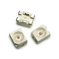
... Encapsulation material: Silicone resin Figure 1. Package Drawing Table 1. Device Selection Guide (T = 25°C) J Color Part Number Blue ASMT-QBBC-NACxE Notes the total luminous flux output as measured with an integrating sphere at mono pulse conditions Tolerance = ±12% Part Numbering System ASMT – 1.9 ± 0.2 Luminous Flux [1] (lm) Min ...

Page 3

... T½ is the off-axis angle where the luminous intensity is ½ the peak intensity. Table 4. Electrical Characteristics (T = 25°C) J Forward Voltage V (Volts Part Number Typ. ASMT-QBBC-NxxxE 3 25°C) ASMT-QxBC-Nxxxx 150 mA 300 mA 570 mW 4 125°C -40°C to +120°C -40°C to +120°C Peak Dominant Wavelength Wavelength O O ...

Page 4

WAVELENGTH - nm Figure 2. Relative Intensity Vs. Wavelength 1.8 1.6 1.4 1.2 1.0 0.8 0.6 0.4 0.2 0 100 150 DC ...

Page 5

D = 0.00 1.00E-05 1.00E-04 1.00E-03 1.00E-02 1.00E-01 1.00E+00 1.00E+01 1.00E+ Time - (S) Figure 7a. Maximum Pulse Current Vs. Ambient Temperature. Derated Based 25° 110°C/W. A J-A 510 ...

Page 6

D Note: Diameter "D" should be smaller than 2.2mm Figure 11. Recommended Pick and Place Nozzle Size CATHODE MARKING SOLDER MASK ANODE A CATHODE C Figure 13. Recommended Soldering Pad ...

Page 7

TRAILER 200 mm MIN. FOR Ø180 REEL. 200 mm MIN. FOR Ø330 REEL. Figure 14. Tape Leader and Trailer Dimensions 4 ± 0.1 4 ± 0.1 +0.1 Ø1.5 –0 3.05 ± 0.1 ALL DIMENSIONS IN mm. Figure 15. Tape Dimensions ...

Page 8

Device Color ( Blue Flux Bin Select ( Individual reel will contain parts from one bin only X Min Flux Bin 2 X Max Flux Bin 3 Flux Bin Limits Bin ID Min. ...

Page 9

Handling Precaution The encapsulation material of the product is made of silicone for better reliability of the product. As silicone is a soft material, please do not press on the silicone or poke a sharp object onto the silicone. These ...

Related keywords