ASMT-QWB2-NEF0E Avago Technologies US Inc., ASMT-QWB2-NEF0E Datasheet

LED COOL WHITE 0.5W 4-PLCC

ASMT-QWB2-NEF0E

Manufacturer Part Number
ASMT-QWB2-NEF0E
Description
LED COOL WHITE 0.5W 4-PLCC
Manufacturer
Avago Technologies US Inc.
Datasheet

Specifications of ASMT-QWB2-NEF0E

Color
White, Cool
Current - Test
150mA
Luminous Flux @ Current - Test
17lm
Current - Max
150mA
Lumens @ Current - Max
17lm
Lumens/watt @ Current - Test
32lm/W
Voltage - Forward (vf) Typ
3.55V
Lens Style/size
Round, 2.4mm
Viewing Angle
120°
Mounting Type
Surface Mount
Package / Case
PLCC-4 - 3.20mm L x 2.80mm W x 1.90mm H
Power Rating
0.5 W
Lead Free Status / RoHS Status
Lead free / RoHS Compliant
Wavelength
-
Lead Free Status / RoHS Status
Lead free / RoHS Compliant, Lead free / RoHS Compliant
Other names
516-2004-2
ASMT-QWB2-Nxxxx
Super 0.5W White Power PLCC-4
Surface Mount LED Indicator
Data Sheet
Description
The Super 0.5W White Power PLCC-4 SMT LED is first
white mid-Power PLCC-4 SMT LEDs using InGaN chip
technology. The package can be driven at high current
due to its superior package design. The product is able
to dissipate the heat more efficiently compared to the
Power PLCC-4 SMT LEDs. These LEDs produce higher light
output with better flux performance compared to the
Power PLCC-4 SMT LED.
The Super 0.5W White Power PLCC-4 SMT LEDs are
designed for higher reliability, better performance, and
operate under a wide range of environmental conditions.
The performance characteristics of these new mid-power
LEDs make them uniquely suitable for use in harsh condi-
tions such as in automotive applications, and in electron-
ics signs and signals.
To facilitate easy pick and place assembly, the LEDs are
packed in EIA-compliant tape and reel. Every reel is
shipped in single intensity and color bin, to provide close
uniformity.
1
CAUTION: ASMT-QWB2-Nxxxx LEDs are Class 1C ESD sensitive. Please observe appropriate precautions
during handling and processing. Refer to Avago Application Note AN-1142 for additional details.
Features
x Industry Standard PLCC 4 platform (3.2 x 2.8 x 1.9mm)
x High reliability package with enhanced silicone resin
x High brightness with optimum flux performance
x Available in Cool White
x High optical efficiency 30lm/W
x Available in 8mm carrier tape and 7 inch reel
x Low Thermal Resistance 60 qC/W
x Super wide viewing angle at 120q
x JEDEC MSL 2a
Applications
1. Interior automotive
2. Exterior automotive
3. Electronic signs and signals
4. Office automation, home appliances, industrial
encapsulation
using InGaN chip technologies
a. Instrument panel backlighting
b. Central console backlighting
c. Navigation and audio system backlighting
d. Dome/Map lighting
e. Push button backlighting
f. Puddle lamp
g. Glove compartment illumination
a. Number plate illumination
b. Rear reverse lamp indicator
a. Decorative lighting
equipment
a. Panel/button backlighting
b. Display backlighting

Related parts for ASMT-QWB2-NEF0E

ASMT-QWB2-NEF0E Summary of contents

Page 1

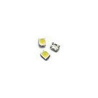
... To facilitate easy pick and place assembly, the LEDs are packed in EIA-compliant tape and reel. Every reel is shipped in single intensity and color bin, to provide close uniformity. CAUTION: ASMT-QWB2-Nxxxx LEDs are Class 1C ESD sensitive. Please observe appropriate precautions during handling and processing. Refer to Avago Application Note AN-1142 for additional details. 1 Features x Industry Standard PLCC 4 platform (3 ...

Page 2

... Encapsulation material: Silicone resin Figure 1. Package Drawing Table 1. Device Selection Guide ( °C) J Luminous Flux, ) Color Part Number Min. Flux (lm) White ASMT-QWB2-NEF0E 11.5 Notes the total luminous flux output as measured with an integrating sphere at mono pulse conditions Tolerance = ±12% Part Numbering System – – ...

Page 3

... Table 4. Electrical Characteristics ( °C) J Forward Voltage V (Volts 150 Part Number Typ. ASMT-QWB2-Nxxxx 3.6 1.0 0.9 0.8 0.7 0.6 0.5 0.4 0.3 0.2 0.1 0.0 380 400 420 440 460 480 500 520 540 560 580 600 620 640 660 680 700 720 740 760 780 WAVELENGTH - nm Figure 2 ...

Page 4

DC FORWARD CURRENT - mA Figure 4. Relative Flux vs. Forward Current 160 140 Rθ = 90°C/W JA 120 Rθ = 110°C/W JA 100 ...

Page 5

D Note: Diameter "D" should be smaller than 2.2mm Figure 9. Recommended Pick and Place Nozzle Size CATHODE MARKING SOLDER MASK ANODE A CATHODE C Figure 11. Recommended Soldering Pad ...

Page 6

TRAILER 200 mm MIN. FOR Ø180 REEL. 200 mm MIN. FOR Ø330 REEL. Figure 12. Tape Leader and Trailer Dimensions 4 ± 0.1 4 ± 0.1 +0.1 Ø1.5 –0 3.05 ± 0.1 ALL DIMENSIONS IN mm. Figure 13. Tape Dimensions ...

Page 7

Handling Precaution The encapsulation material of the product is made of silicone for better reliability of the product. As silicone is a soft material, please do not press on the silicone or poke a sharp object onto the silicone. These ...

Page 8

Color Bin Limits Bin ID Limits (Chromaticity Coordinates 0.296 0.291 y 0.259 0.268 2 x 0.291 0.285 y 0.268 0.279 3 x 0.313 0.310 y 0.284 0.297 4 x 0.310 0.307 y 0.297 0.312 5 x 0.330 0.330 ...

Related keywords