BXRA-N0800-00000 Bridgelux, BXRA-N0800-00000 Datasheet - Page 4
BXRA-N0800-00000
Manufacturer Part Number
BXRA-N0800-00000
Description
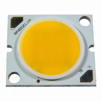
LED ARRAY NEUTRAL WHITE 880LM
Manufacturer
Bridgelux
Series
LEDr
Type
Without Connectorr
Specifications of BXRA-N0800-00000
Color
White, Neutral
Luminous Flux @ Current - Test
880 lm
Current - Test
1.2A
Current - Max
2A
Driver Circuitry
No
Voltage
13V
Wavelength
4100K
Configuration
Square
With Connector
No
Voltage - Input
13V
Led Color
Neutral White
Luminous Flux @ Test
880lm
Cct
4750K
Forward Current @ Test
1.2A
Forward Current If Max
2A
Forward Voltage @ Test
13V
Viewing Angle
120°
Led Mounting
SMD
Rohs Compliant
Yes
Lead Free Status / RoHS Status
Lead free / RoHS Compliant
Interface
-
Power - Input
-
Other names
976-1028


Minor Product Change Policy
The rigorous qualification testing on products offered by Bridgelux provides performance assurance.
Slight cosmetic changes that do not affect form, fit, or function may occur as Bridgelux continues product
optimization.
CAUTION: CONTACT WITH OPTICAL AREA
Contact with the resin area should be avoided. Applying stress to the resin area can result in damage to
the product.
CAUTION: EYE SAFETY
Eye safety classification for the use of Bridgelux LED Arrays is contained in the CIE S 009/E2002
Photobiological Safety of Lamps and Lamp Systems specification. Bridgelux LED Arrays are classified
under section 6 lamp classification as Risk Group 2 (Moderate Risk). Please use appropriate
precautions. It is important that employees working with LEDs are trained to use them safely. Luminaire
manufacturers should refer to CIE S 009/E2002 to establish the classification of their product.
CAUTION: RISK OF BURN
Do not touch the LED Array or resin area during operation. Allow the LED Array to cool for a sufficient
period of time before handling. The LED Array may reach elevated temperatures such that it can burn
skin when touched.
Case Temperature Measurement Point
A case temperature measurement point location is included on the top surface of the Bridgelux LED
Arrays. The location of this measurement point is indicated in the mechanical dimensions section of this
data sheet.
The purpose of this measurement point is to allow the user access to a measurement point closely linked
to the true case temperature on the back surface of the LED array. Once the LED array is installed, it is
challenging to measure the back surface of the array, or true case temperature. Measuring the top
surface of the product can lead to inaccurate results due to the poor thermal conductivity of the top layers
of the array such as the solder mask and other materials.
Bridgelux has provided the case temperature measurement location in a manner which closely ties it to
the true case temperature of the array under steady state operation. Deviations between thermal
measurements taken at the point indicated and the back of the LED array differ by less than 1°C,
providing a robust method to testing thermal operation once the product is installed.
Bridgelux LED Array Data Sheet DS10 (10/11/11)
Page 4 of 35
Related parts for BXRA-N0800-00000
Image
Part Number
Description
Manufacturer
Datasheet
Request
R

Part Number:
Description:
HIGH BRIGHTNESS LED, COOL WHITE, 5600LM
Manufacturer:
Bridgelux
Datasheet:

Part Number:
Description:
HIGH BRIGHTNESS LED,NEUTRAL WHITE,4400LM
Manufacturer:
Bridgelux
Datasheet:
Part Number:
Description:
HIGH BRIGHTNESS LED,NEUTRAL WHITE,7000LM
Manufacturer:
Bridgelux
Datasheet:
Part Number:
Description:
HIGH BRIGHTNESS LED, WARM WHITE, 4000LM
Manufacturer:
Bridgelux
Datasheet:
Part Number:
Description:
HIGH BRIGHTNESS LED, WARM WHITE, 3700LM
Manufacturer:
Bridgelux
Datasheet:
Part Number:
Description:
HIGH BRIGHTNESS LED, WARM WHITE, 6300LM
Manufacturer:
Bridgelux
Datasheet:
Part Number:
Description:
HIGH BRIGHTNESS LED, WARM WHITE, 5800LM
Manufacturer:
Bridgelux
Datasheet:
Part Number:
Description:
HIGH BRIGHTNESS LED, COOL WHITE, 8800LM
Manufacturer:
Bridgelux
Datasheet:
Part Number:
Description:
HIGH BRIGHTNESS LED, WARM WHITE, 3600LM
Manufacturer:
Bridgelux
Datasheet:
Part Number:
Description:
HIGH BRIGHTNESS LED, WARM WHITE, 3300LM
Manufacturer:
Bridgelux
Datasheet:
Part Number:
Description:
HIGH BRIGHTNESS LED, WARM WHITE, 5650LM
Manufacturer:
Bridgelux
Datasheet:
Part Number:
Description:
HIGH BRIGHTNESS LED, WARM WHITE, 5200LM
Manufacturer:
Bridgelux
Datasheet:

Part Number:
Description:
HIGH BRIGHTNESS LED, WARM WHITE, 295LM
Manufacturer:
Bridgelux
Datasheet:
Part Number:
Description:
HIGH BRIGHTNESS LED, WARM WHITE, 460LM
Manufacturer:
Bridgelux
Datasheet:
Part Number:
Description:
HIGH BRIGHTNESS LED, WARM WHITE, 460LM
Manufacturer:
Bridgelux
Datasheet: