3500S-2-102 Bourns Inc., 3500S-2-102 Datasheet
3500S-2-102
Manufacturer Part Number
3500S-2-102
Description
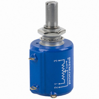
POT 1K OHM 7/8" WW 2W +/-50 PPM
Manufacturer
Bourns Inc.
Series
3500r
Datasheet
1.3500S-2-103L.pdf
(2 pages)
Specifications of 3500S-2-102
Resistance (ohms)
1K
Power (watts)
2W
Tolerance
±3%
Temperature Coefficient
±50ppm/°C
Number Of Turns
10
Rotation
3600°
Adjustment Type
Side Adjustment
Resistive Material
Wirewound
Termination Style
Solder Lug
Actuator Length
20.64mm
Actuator Type
Slotted Shaft
Actuator Diameter
6.34mm
Package / Case
Round - 0.875" Dia x 1.000" H (22.23mm x 25.40mm)
Resistance In Ohms
1.00K
Resistance
1 KOhms
Power Rating
2 Watts
Element Type
Wire Wound
Shaft Type
Slotted
Shaft Length
20.64 mm
Shaft Diameter
6.34 mm
Dimensions
22.23 mm Dia. x 25.4 mm L
Product
Precision Potentiometers
Resolution
0.03 %
Lead Free Status / RoHS Status
Contains lead / RoHS non-compliant
Available stocks
Company
Part Number
Manufacturer
Quantity
Price
Company:

Part Number:
3500S-2-102L
Manufacturer:
BOURNS
Quantity:
20 000
Company:
Part Number:
3500S-2-102L
Manufacturer:
BOURNS
Quantity:
20 000
Company:
Part Number:
3500S-2-102L
Manufacturer:
BOURNS
Quantity:
1 000


Standard Resistance Range .................................................... 50 to 200 K ohms ..........................................1 K to 200 K ohms
Total Resistance Tolerance ...................................................... ±3 % ..............................................................±10 %
Independent Linearity .............................................................. ±0.20 % .........................................................±0.25 %
Effective Electrical Angle ......................................................... 3600 ° +10 °, -0 ° ...........................................3600 ° +10 °, -2 °
Absolute Minimum Resistance/Minimum Voltage ................... 1 ohm or 0.1 % maximum .............................0.2 % maximum
Noise ...................................................................................... 100 ohms ENR maximum ..............................Output smoothness 0.1 % max.
Dielectric Withstanding Voltage (MIL-STD-202, Method 301)
Power Rating (Voltage Limited By Power Dissipation or 325 VAC, Whichever Is Less)
Insulation Resistance (500 VDC) ............................................. 1,000 megohms minimum .............................1,000 megohms minimum
Resolution ............................................................................... See recommended part nos ..........................Essentially infi nite
Operating Temperature Range ................................................ +1 °C to +125 °C ...........................................+1 °C to +125 °C
Storage Temperature Range ................................................... -65 °C to +125 °C ..........................................-65 °C to +125 °C
Temperature Coeffi cient Over
Vibration .................................................................................. 20 G ...............................................................20 G
Shock ...................................................................................... 100 G .............................................................100 G
Load Life .................................................................................. 1,000 hours, 2 watts ......................................1,000 hours, 2 watts
Rotational Life (No Load) ......................................................... 2,000,000 shaft revolutions
Moisture Resistance (MIL-STD-202, Method 103, Condition B)
IP Rating .................................................................................. IP 65 ..............................................................IP 65
Stop Strength ......................................................................................................................................................................... 67.8 N-cm (96 oz.-in.) minimum
Mechanical Angle ..........................................................................................................................................................................................3600 ° +10 °, -0 °
Torque (Starting & Running) .................................................................................................................................................. 0.42 N-cm (0.6 oz.-in.) maximum
Shaft Runout .....................................................................................................................................................................................0.05 mm (0.002 in.) T.I.R.
Lateral Runout ...................................................................................................................................................................................0.13 mm (0.005 in.) T.I.R.
Shaft End Play ...................................................................................................................................................................................0.13 mm (0.005 in.) T.I.R.
Shaft Radial Play ...............................................................................................................................................................................0.08 mm (0.003 in.) T.I.R.
Pilot Diameter Runout .......................................................................................................................................................................0.05 mm (0.002 in.) T.I.R.
Backlash ........................................................................................................................................................................................................... 1.0 ° maximum
Weight .................................................................................................................................................................................................... Approximately 28 gm
Terminals ................................................................................................................................... Gold-plated solder lugs or turrets (see Product Dimensions)
Soldering Condition
Marking ................................... Manufacturer’s name and part number, resistance value and tolerance, linearity tolerance, wiring diagram, and date code.
Ganging (Multiple Section Potentiometers) ................................................................................................................................................... 2 cups maximum
Hardware ..............................................................................One lockwasher (H-37-2) and one mounting nut (H-38-2) is shipped with each potentiometer.
1
2
At room ambient: +25 °C nominal and 50 % relative humidity nominal, except as noted.
Consult manufacturer for complete specifi cation details.
Part Number
3500S-1-102L
3500S-1-502L
3500S-1-103L
3500S-2-102L
3500S-2-502L
3500S-2-103L
Electrical Characteristics
Sea Level ............................................................................. 1,500 VAC minimum ......................................1,500 VAC minimum
70,000 Feet .......................................................................... 400 VAC minimum .........................................400 VAC minimum
+70 °C.................................................................................. 2 watts ...........................................................2 watts
+125 °C................................................................................ 0 watt .............................................................0 watt
Environmental Characteristics
Storage Temperature Range
Wiper Bounce ...................................................................... 0.1 millisecond maximum ..............................0.1 millisecond maximum
Total Resistance Shift .......................................................... ±2 % maximum .............................................±2 % maximum
Voltage Ratio Shift ............................................................... ±0.1 % maximum ..........................................±0.1 % maximum
Total Resistance Shift .......................................................... ±2 % maximum .............................................±5 % maximum
Total Resistance Shift .......................................................... ±5 % maximum .............................................±5 % maximum
Total Resistance Shift .......................................................... ±2 % maximum .............................................±5 % maximum
Mechanical Characteristics
Mounting................................................................................................................................................................. 170-200 N-cm (15-18 lb.-in.) maximum
Manual Soldering .........................................................96.5Sn/3.0Ag/0.5Cu solid wire or no-clean rosin cored wire; 370 °C (700 °F) max. for 3 seconds
Wave Soldering.................................................................................. 96.5Sn/3.0Ag/0.5Cu solder with no-clean fl ux; 260 °C (500 °F) max. for 5 seconds
Wash processes ......................................................................................................................................................................................Not recommended
Recommended Part Numbers
Resistance (Ω)
10,000
10,000
1,000
5,000
1,000
5,000
2
1
.............................................. ±50 ppm/°C maximum/unit ...........................±100 ppm/°C maximum/unit
Resolution (%)
1
.030
.018
.019
.030
.018
.019
1
Features
■
■
■
■
■
■
3500/3501 - Precision Potentiometer
Part Number
3501H-1-102L
3501H-1-502L
3501H-1-103L
Bushing mount
Sealable
Non-standard features and specifi cations available
Optional high torque feature
Optional center tap feature
Gangable
3500 Wirewound Element
(whichever is greater)
Resistance (Ω)
10,000
1,000
5,000
Customers should verify actual device performance in their specifi c applications.
2
..........................4,000,000 shaft revolutions
*RoHS Directive 2002/95/EC Jan 27, 2003 including Annex
3501 Hybritron
BOLDFACE LISTINGS ARE IN STOCK AND READILY
AVAILABLE THROUGH DISTRIBUTION.
FOR OTHER OPTIONS CONSULT FACTORY.
ROHS IDENTIFIER:
L = COMPLIANT
BLANK = NON-COMPLIANT
Specifi cations are subject to change without notice.
®
Element
Related parts for 3500S-2-102
Image
Part Number
Description
Manufacturer
Datasheet
Request
R

Part Number:
Description:
POT 10K OHM 7/8" WW 2W+/-50 PPM
Manufacturer:
Bourns Inc.
Datasheet:
Part Number:
Description:
POT 1K OHM 7/8" WW 2W+/-50 PPM
Manufacturer:
Bourns Inc.
Datasheet:
Part Number:
Description:
POT 5.0K OHM 7/8" WW 2W+/-50 PPM
Manufacturer:
Bourns Inc.
Datasheet:

Part Number:
Description:
POT 100K OHM 7/8" RD WW
Manufacturer:
Bourns Inc.
Datasheet:
Part Number:
Description:
POT 2.0K OHM 7/8" RD WW
Manufacturer:
Bourns Inc.
Datasheet:
Part Number:
Description:
POT 10K OHM 7/8" WW 2W +/-50 PPM
Manufacturer:
Bourns Inc.
Datasheet:
Part Number:
Description:
POT 5K OHM 7/8" WW 2W +/-50 PPM
Manufacturer:
Bourns Inc.
Datasheet:
Part Number:
Description:
POT 200 OHM 7/8" RD WW
Manufacturer:
Bourns Inc.
Datasheet:
Part Number:
Description:
POT 20K OHM 7/8" RD WW
Manufacturer:
Bourns Inc.
Datasheet:
Part Number:
Description:
POT 500 OHM 7/8" RD WW
Manufacturer:
Bourns Inc.
Datasheet:

Part Number:
Description:
Manufacturer:
Bourns, Inc.
Datasheet:
Part Number:
Description:
11mm Potentiometer
Manufacturer:
Bourns, Inc.
Datasheet:
3500S-2-102 Summary of contents
Page 1
... Consult manufacturer for complete specifi cation details. Recommended Part Numbers Part Number Resistance (Ω) Resolution (%) 3500S-1-102L 1,000 .030 3500S-1-502L 5,000 .018 3500S-1-103L 10,000 .019 3500S-2-102L 1,000 .030 3500S-2-502L 5,000 .018 3500S-2-103L 10,000 .019 Features ■ Bushing mount ■ Sealable ■ ...
Page 2
... R MAX. ADJUSTMENT SLOT .81 WIDE X (.032) .81 ± .25 DEEP 22.23 (.032 ± .010) (7/8) NOTE: SHAFT LENGTH VARIATIONS 11/16 3500S-1-RC (17.46) 13/16 3500S-2-RC (20.64) 13/16 3501H-1-RC (20.64) TOLERANCES: EXCEPT WHERE NOTED .25 .13 DECIMALS: .XX ± .XXX ± (.010), (.005) FRACTIONS: ±1/64 MM DIMENSIONS: (IN.) ...