TS53YL502MR10 Vishay, TS53YL502MR10 Datasheet - Page 3
TS53YL502MR10
Manufacturer Part Number
TS53YL502MR10
Description
POT 5.0K OHM 4MM SQ CERM SMT
Manufacturer
Vishay
Series
TS53Yr
Datasheet
1.TS53YJ502MR10.pdf
(5 pages)
Specifications of TS53YL502MR10
Temperature Coefficient
±100ppm/°C
Resistance (ohms)
5K
Power (watts)
0.25W, 1/4W
Taper
Linear
Tolerance
±20%
Number Of Turns
Single
Adjustment Type
Top Adjustment
Mounting Type
Surface Mount
Resistive Material
Cermet
Package / Case
Square - 0.197" L x 0.197" W x 0.106" H (5.00mm x 5.00mm x 2.70mm)
Resistance In Ohms
5.00K
No. Of Turns
1
Resistance Tolerance
± 20%
Power Rating
250mW
Potentiometer Mounting
SMD
Terminal Type
PCB Surface Mount
Resistance
5 KOhms
Operating Temperature Range
- 55 C to + 125 C
Element Type
Cermet
Dimensions
5 mm W x 5 mm L x 2.7 mm H
Product
Single Turn Trimmers
Termination Style
SMD/SMT
Track Resistance
5kohm
Termination Type
SMD
Rohs Compliant
Yes
Lead Free Status / RoHS Status
Lead free / RoHS Compliant
Lead Free Status / RoHS Status
Lead free / RoHS Compliant, Lead free / RoHS Compliant
Other names
TS53YL-5.0KTR
Available stocks
Company
Part Number
Manufacturer
Quantity
Price
Company:

Part Number:
TS53YL502MR10
Manufacturer:
VISHAY
Quantity:
30 000


www.vishay.com
20
TS53
Vishay Sfernice
RESISTANCE
PERFORMANCE
TESTS
Load Life
Climatic Sequence
Long Term Damp Heat
Thermal Shock
Rotational Life (Electrical and Mechanical)
Shock
Vibration
STANDARD RESISTANCE ELEMENT DATA
STANDARD
VALUES
100K
200K
500K
10K
20K
50K
100
200
500
1M
1K
2K
5K
10
20
50
Ω
AT 70 °C
POWER
MAX.
0.25
0.25
0.20
0.08
0.04
W
LINEAR LAW
WORKING
VOLTAGE
MAX.
1.58
2.24
3.54
5.00
7.07
11.2
15.8
22.4
35.4
50.0
70.7
112
158
200
200
200
V
MAX. CUR.
THROUGH
ELEMENT
Surface Mount Miniature Trimmers
158
112
mA
For technical questions, contact: sfer@vishay.com
3.5
2.2
1.6
1.0
0.4
0.2
71
50
35
22
16
11
7
5
90'/30' - ambient temperature + 70 °C
Single-Turn Cermet Sealed
3 successive shocks in 3 directions
Temperature 40 °C - RH 93 %
Phase D damp heat 5 cycles
55 °C to + 125 °C - 5 cycles
1000 hours at rated power
0.75 mm or 10 g - 6 hours
TYPICAL
Phase A dry heat 125 °C
100 cycles - rated power
+ 125 °C
ppm/°C
- 55 °C
± 100
Phase C cold - 55 °C
TCR
Phase B damp heat
CONDITIONS
50 g - 11 ms
10 - 55 Hz
56 days
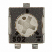
MARKING
VISHAY trademark, ohmic value, manufacturing date.
The ohmic value is indicated by a 3 figure code, the first two
are significant figures, the third one is the multiplier.
Example:
SOLDERING RECOMMENDATIONS
See Application notes
CAUTION
Reflow soldering must be done within 72 h while stored
under a max. temperature of 30 °C, 60 % RH after opening
the dry pack envelope.
RECOMMENDED METHOD OF STORAGE
Dry box storage is recommended as soon as the hermetic
bag has been opened to prevent moisture absorption. The
following conditions should be observed, if dry boxes are not
available:
• Storage temperature 10 °C to 30 °C
• Storage humidity ≤ 60 % RH max.
After more than 72 h under these conditions, moisture
content will be too high for reflow soldering.
In case of moisture absorption, the devices will recover to the
former condition by drying under the following condition:
192 h at 40 °C + 5 °C/- 0 °C and < 5 % RH (dry air/nitrogen) or
96 h at 60 °C + 5 °C and < 5 % RH for all device containers
(not suitable for reel) or
24 h at 125 °C + 5 °C (not suitable for reel)
± 2 %
Contact resistance variation: ΔR < 1 % Rn
± 2 %
± 2 %
Dielectric strength: 1000 V RMS
Insulation resistance: > 10
± 1 %
± (3 % + 5 Ω)
± 1 %
± 1 %
TYPICAL VALUES AND DRIFTS
100 = 10
101 = 100
102 = 1000
503 = 50 000
ΔRT
RT
(%)
Ω
Ω
Ω
Ω
Document Number: 51008
4
MΩ
Revision: 22-Dec-08
± 3 %
± 3 %
± 3 %
ΔR
ΔV
ΔV
ΔV
R
V
V
V
1-2
1-2
1-2
1-3
1-2
1-3
1-2
1-3
(%)
≤ ± 2 %
≤ ± 1 %
≤ ± 1 %
Related parts for TS53YL502MR10
Image
Part Number
Description
Manufacturer
Datasheet
Request
R

Part Number:
Description:
Surface Mount Miniature Trimmers Single-turn Cermet Sealed
Manufacturer:
Vishay
Datasheet:
Part Number:
Description:
357-036-542-201 CARDEDGE 36POS DL .156 BLK LOPRO
Manufacturer:
Vishay
Datasheet:
Part Number:
Description:
357-036-542-201 CARDEDGE 36POS DL .156 BLK LOPRO
Manufacturer:
Vishay
Datasheet:
Part Number:
Description:
357-036-542-201 CARDEDGE 36POS DL .156 BLK LOPRO
Manufacturer:
Vishay
Datasheet:
Part Number:
Description:
357-036-542-201 CARDEDGE 36POS DL .156 BLK LOPRO
Manufacturer:
Vishay
Datasheet:
Part Number:
Description:
357-036-542-201 CARDEDGE 36POS DL .156 BLK LOPRO
Manufacturer:
Vishay
Datasheet:
Part Number:
Description:
357-036-542-201 CARDEDGE 36POS DL .156 BLK LOPRO
Manufacturer:
Vishay
Datasheet:
Part Number:
Description:
357-036-542-201 CARDEDGE 36POS DL .156 BLK LOPRO
Manufacturer:
Vishay
Datasheet:
Part Number:
Description:
357-036-542-201 CARDEDGE 36POS DL .156 BLK LOPRO
Manufacturer:
Vishay
Datasheet:
Part Number:
Description:
357-036-542-201 CARDEDGE 36POS DL .156 BLK LOPRO
Manufacturer:
Vishay
Datasheet:
Part Number:
Description:
357-036-542-201 CARDEDGE 36POS DL .156 BLK LOPRO
Manufacturer:
Vishay
Datasheet:
Part Number:
Description:
357-036-542-201 CARDEDGE 36POS DL .156 BLK LOPRO
Manufacturer:
Vishay
Datasheet:
Part Number:
Description:
357-036-542-201 CARDEDGE 36POS DL .156 BLK LOPRO
Manufacturer:
Vishay
Datasheet:
Part Number:
Description:
357-036-542-201 CARDEDGE 36POS DL .156 BLK LOPRO
Manufacturer:
Vishay
Datasheet:
Part Number:
Description:
357-036-542-201 CARDEDGE 36POS DL .156 BLK LOPRO
Manufacturer:
Vishay
Datasheet: