MPD6D107S Murata Electronics North America, MPD6D107S Datasheet - Page 9
MPD6D107S
Manufacturer Part Number
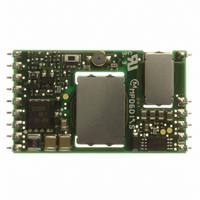
MPD6D107S
Description
CONV DC/DC 10W 3.3VOUT 3A SMT
Manufacturer
Murata Electronics North America
Series
MPDr
Type
Isolatedr
Datasheet
1.MPD6D107S.pdf
(15 pages)
Specifications of MPD6D107S
Output
3.3V
Number Of Outputs
1
Power (watts)
10W
Mounting Type
Surface Mount
Voltage - Input
36 ~ 75V
Package / Case
18-DIP SMD Module (15 Leads)
1st Output
3.3 VDC @ 3A
Size / Dimension
1.47" L x 0.88" W x 0.17" H (37.3mm x 22.4mm x 4.2mm)
Power (watts) - Rated
10W
Operating Temperature
-40°C ~ 85°C
Efficiency
89%
Approvals
CE, cUL, UL, TUV
Lead Free Status / RoHS Status
Lead free / RoHS Compliant
3rd Output
-
2nd Output
-
4th Output
-
Other names
490-4588


1. This datasheet is downloaded from the website of Murata Manufacturing co., ltd. Therefore, it’ s specifications are subject to change or our
2. This datasheet has only typical specifications because there is no space for detailed specifications. Therefore, please approve our product
Note:
products in it may be discontinued without advance notice. Please check with our sales representatives or product engineers before ordering.
specifications or transact the approval sheet for product specifications before ordering.
9. 3. Reliability
9.2.6. Synchronous Turn-on/off
9.3.1. Humidity Test
9.3.2. Thermal Cycle Test
9.3.3. Vibration
9.3.4. Mechanical Shock
9.3.5. Soldering Heat Resistance
9.3.6. Lead Pin Strength
9.3.7. Solderability of Leads
The Isolated DC-DC Converters running for multiple and / or parallel operation are enable to
synchronize turn-on/off timing among the running converters, of which the input voltage detection
circuits are unified to the detection voltage of a certain Isolated DC-DC Converter. Every PO pin is
necessary to be connected for multiple and/or parallel operation. Maximum number running DC-DC
Converters is 10pcs.To connect more than 10,please consult Murata.
Parts are subjected to a temperature 40°C
Return the parts to room temperature (25°C) for 4 hours and measure. The initial values under item
9.1. should be met. (JIS-C-0022)
Then tested products are left for 2 hours.
Immerse the part of lead where it is to be soldered on a motherboard in a solder bath of 260
for 3
Parts are subjected to 5 cycle of the following.
The parts are placed in room temperature (25°C) for 2 hours and are measured.
The initial values under item 9.1. should be met.
No damage in appearance and no deviation from electrical characteristics(9.1.).
20G, 1 time for each X,Y,Z directions.
No damage in appearance and no deviation from electrical characteristics(9.1.).
There is no damage in appearance and no deviation from electrical characteristics in clause 9.1.
10 to 55Hz, 1.5mm amplitude, 1 hour for each each of X,Y,Z directions.
The lead pins will be immersed in the Isopropyl Alcohol (JIS K 1522) with Rosin (JIS K 5902)
solution (the concentration of Rosin will be allowed 10wt% to 35wt%, and normally approx.25wt%
will be used without any specific requirement.). Then the lead pins will be immersed in the solder
H63A (JIS Z 3282) solution at the temperature of 230°C
completely. The solder will adhere to over 75% of immersed area.
Strain a lead pin by gradual-increasingly 5.0N along axial direction; withstand for 5s.
No damage on a lead pin.
±
Step
0.5s.
1
2
3
4
Room Temp.
Room Temp.
+85±3°C
Condition
-40±3°C
5∼10 minutes
5∼10 minutes
30 minutes
30 minutes
±
Time
2°C with 90∼95% for 100 hours.
±
5°C for 3
±
0.5seconds, and pulled up
MPD6D10*S Specification
±
5°C
2010.5.7
9
Related parts for MPD6D107S
Image
Part Number
Description
Manufacturer
Datasheet
Request
R

Part Number:
Description:
CONV DC/DC 5W 5.0VOUT 1A SMT
Manufacturer:
Murata Electronics North America
Datasheet:

Part Number:
Description:
CONV DC/DC 5W 3.3VOUT 1.5A SMT
Manufacturer:
Murata Electronics North America
Datasheet:

Part Number:
Description:
CONV DC/DC 10W 12VOUT .8A SMT
Manufacturer:
Murata Electronics North America
Datasheet:

Part Number:
Description:
CONV DC/DC 10W 5.0VOUT 2A SMT
Manufacturer:
Murata Electronics North America
Datasheet:

Part Number:
Description:
CONV DC/DC 15W 3.3VOUT 4.5A SMT
Manufacturer:
Murata Electronics North America
Datasheet:

Part Number:
Description:
CONV DC/DC 50W 3.3VOUT 15A PIN
Manufacturer:
Murata Electronics North America
Datasheet:

Part Number:
Description:
CONV DC/DC 50W 5.0VOUT 10A SMT
Manufacturer:
Murata Electronics North America
Datasheet:

Part Number:
Description:
CONV DC/DC 10W 1.8VOUT 3A SMT
Manufacturer:
Murata Electronics North America
Datasheet:

Part Number:
Description:
CONV DC/DC 10W 2.5VOUT 3A SMT
Manufacturer:
Murata Electronics North America
Datasheet:

Part Number:
Description:
CONV DC/DC 15W 1.8VOUT 4.5A SMT
Manufacturer:
Murata Electronics North America
Datasheet:

Part Number:
Description:
BUZZER PIEZO 25VP-P SMD
Manufacturer:
Murata Electronics North America

Part Number:
Description:
CAP 4-ARRAY 680PF 100V X7R 1206
Manufacturer:
Murata Electronics North America
Datasheet:
Part Number:
Description:
CAP 4-ARRAY 1000PF 100V X7R 1206
Manufacturer:
Murata Electronics North America
Datasheet:
Part Number:
Description:
CAP 4-ARRAY 1800PF 100V X7R 1206
Manufacturer:
Murata Electronics North America
Datasheet:
Part Number:
Description:
CAP 4-ARRAY 68000PF 16V X7R 1206
Manufacturer:
Murata Electronics North America
Datasheet: