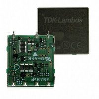
CC1R5-1212DF-E TDK Corporation, CC1R5-1212DF-E Datasheet

CC1R5-1212DF-E
Specifications of CC1R5-1212DF-E
CC1R51212DFE
Related parts for CC1R5-1212DF-E
CC1R5-1212DF-E Summary of contents
Page 1
... S: Single output, D: Double output 03: 3. 12: 12V 05 12: 12V / 24: 24V / 48: 48V 1R5: 1. 6:6W / 10: 10W / 15: 15W / 25: 25W Conformity to RoHS Directive ∗2 ∗2 12V(15V ) ±12V(15V ) or 24V, 30V CC1R5-0512Sx-E CC1R5-0512Dx-E CC1R5-1212Sx-E CC1R5-1212Dx-E CC1R5-2412Sx-E CC1R5-2412Dx-E CC1R5-4812Sx-E CC1R5-4812Dx-E CC3-0512Sx-E CC3-0512Dx-E CC3-1212Sx-E CC3-1212Dx-E CC3-2412Sx-E CC3-2412Dx-E CC3-4812Sx-E CC3-4812Dx-E CC6-0512Sx-E ...
Page 2
... CC1R5 Type ELECTRICAL CHARACTERISTICS Input Output ∗2 Part No. voltage voltage (V) (V) ∗1 CC1R5-0503Sx -E 4 3.3±3% CC1R5-0505Sx-E 4 5±3% 4 12±3% CC1R5-0512Sx-E ∗7 4 15±3% 4 ±12±5% ∗6 CC1R5-0512Dx-E 4 ±15±5% CC1R5-1203Sx 3.3±3% CC1R5-1205Sx 5± 12±3% CC1R5-1212Sx-E ∗ 15± ±12±5% ∗ ...
Page 3
... CC1R5 Type SHAPES AND DIMENSIONS CC1R5-xxxxxF-E (DIP TYPE) 12.7 16.51 1.905 12.7 1.905 7-0.3×0 CC1R5-xxxxxR-E (SMD TYPE) 16.51 19.81 1.8 1 7-0.3×0 CONNECTIONS CC1R5-xxxxSx-E +Vin +Vout TRM 5 RC –Vout –Vin • All specifications are subject to change without notice. 16.6±0.2 t=0 ...
Page 4
CC3 Type(DIP, SMD Types) ELECTRICAL CHARACTERISTICS Input Output ∗2 Part No. voltage voltage (V) (V) ∗1 CC3-0503Sx -E 4 3.3±3% CC3-0505Sx-E 4 5±3% 4 12±3% CC3-0512Sx-E ∗7 4 15±3% 4 ...
Page 5
CC3 Type(SIP Type) ELECTRICAL CHARACTERISTICS Input Output ∗1 Part No. voltage voltage (V) (V) CC3-0503SS-E 4 3.3±3% CC3-0505SS-E 4 5±3% 4 12±3% CC3-0512SS-E ∗6 4 15±3% 4 ±12±5% ∗5 CC3-0512DS-E ...
Page 6
CC3 Type(DIP, SMD Types) SHAPES AND DIMENSIONS CC3-xxxxxF-E (DIP TYPE) 17.78 22.86 2.54 17.78 2. 7-0.3×0 CC3-xxxxxR-E (SMD TYPE) 22.86 26.16 1.8 1 7-0.3×0.6 6 ...
Page 7
CC3 Type(SIP Type) SHAPES AND DIMENSIONS CC3-xxxxxS-E (SIP TYPE) 2. 22.86 27 SMD location CONNECTIONS CC3-xxxxSS ...
Page 8
CC6 Type ELECTRICAL CHARACTERISTICS Input Output ∗2 Part No. voltage voltage (V) (V) ∗1 CC6-0503Sx -E 4 3.3±3% CC6-0505Sx-E 4 5±3% 4 12±3% CC6-0512Sx-E ∗7 4 15±3% 4 ±12±5% ∗6 ...
Page 9
CC6 Type SHAPES AND DIMENSIONS CC6-xxxxxF-E (DIP TYPE) 17.78 22.86 2.54 2. 7-0.3×0 CC6-xxxxxR-E (SMD TYPE) 22.86 26.16 1.8 1 7-0.3×0 CONNECTIONS ...
Page 10
CC10 Type ELECTRICAL CHARACTERISTICS Input Output ∗2 Part No. voltage voltage (V) (V) ∗1 CC10-0503Sx -E 4 3.3±3% CC10-0505Sx-E 4 5±3% 4 12±3% CC10-0512Sx-E ∗7 4 15±3% 4 ±12±5% ∗6 ...
Page 11
CC10 Type SHAPES AND DIMENSIONS CC10-xxxxxF-E (DIP TYPE) 25.4 35.56 5.08 25.4 5. 7-0.3×0 CC10-xxxxxR-E (SMD TYPE) 35.56 38.86 1 7-0.3×0 CONNECTIONS ...
Page 12
CC15 Type ELECTRICAL CHARACTERISTICS Input Output ∗2 Part No. voltage voltage (V) (V) ∗1 CC15-2403Sx - 3.3/– 4500 CC15-2405Sx 5.0/– 3000 ∗1 An "x" within the ...
Page 13
CC15 Type SHAPES AND DIMENSIONS CC15-xxxxSF-E (DIP TYPE) 38.1 6.075 25.4 6.075 37. 17-0.3×0 CC15-xxxxSR-E (SMD TYPE) 38.1 40.9 ...
Page 14
CC25 Type ELECTRICAL CHARACTERISTICS Input Output ∗2 Part No. voltage voltage (V) (V) ∗1 CC25-2403Sx - 3.3/– 7500 CC25-2405Sx 5.0/– 5000 ∗1 An "x" within the ...
Page 15
CC25 Type SHAPES AND DIMENSIONS CC25-xxxxSF-E (DIP TYPE) 43.2 6.075 30.5 6.075 42. 25-0.3×0 ...
Page 16
Control Functions/Connections REMOTE CONTROL TERMINAL(RC) (DIP/SMD MODELS) 1.5 to 10W Types It is recommended to use an open collector as the control method for the remote control terminal. If other methods are necessary, please contact TDK first. In addition, please ...
Page 17
Control Functions/Connections With the ±12V, 24V single output is possible by opening the COM terminal and TRM terminal. Also, 30V single output is possible when opening the COM terminal and connecting the TRM terminal with the –Vout terminal. DIP/SMD Models ...
Page 18
Control Functions/Connections SIP Model Connecting –Vout Part No. Fig. with Ra ∗1 CC3–xx03SS–E 3.3 to 3.67V 13 ∗2 CC3–xx05SS– ∗3 CC3–xx12SS– 15V 13 ∗4 CC3–xx12DS–E ±12 to ±15V 15 Calculate the output voltage Vout(V) ...
Page 19
... Please keep in mind that if the capacitor installed at the output location has a larger capacity than shown in the following value capacitors with low impedance are connected parallel much, converter operation may be unstable. Part No. CC1R5-xx03Sx-E +Vin +Vout CC1R5-xx05Sx-E CC1R5-xx12Sx-E CC1R5-xx12Dx-E CC3-xx03Sx-E –Vin –Vout CC3-xx05Sx-E CC3-xx12Sx-E CC3-xx12Dx-E CC6-xx03Sx-E CC6-xx05Sx-E CC6-xx12Sx-E ...
Page 20
Noise Reduction Measurement/Protection/Connections COMMON MODE NOISE Products with under 10W contain capacitors that are not con- nected between the first and second. Therefore, in order to reduce common mode noise, please connect a capacitor with about 1,000pF between the first ...
Page 21
Soldering Conditions/Cleaning Conditions SOLDERING CONDITIONS DIP and SIP Models Make sure to perform soldering to the PC board under the follow- ing conditions. Soldering DIP 260°C, for 10 seconds max. Soldering iron 380°C, for 3 seconds max. SMD Model Lead-free ...


