CC6-2412SF-E TDK Corporation, CC6-2412SF-E Datasheet - Page 20
CC6-2412SF-E
Manufacturer Part Number
CC6-2412SF-E
Description
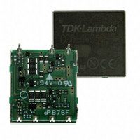
CONV DC/DC 6W SNGL 24V 12V PCB
Manufacturer
TDK Corporation
Series
CC-Er
Type
Isolatedr
Datasheets
1.CC1R5-0505SF-E.pdf
(2 pages)
2.CC1R5-0505SF-E.pdf
(21 pages)
3.CC6-2412DF-E.pdf
(18 pages)
4.CC10-2412DF-E.pdf
(3 pages)
Specifications of CC6-2412SF-E
Output
12 ~ 15V
Number Of Outputs
1
Power (watts)
6W
Mounting Type
Through Hole
Voltage - Input
18 ~ 36V
Package / Case
7-DIP Module
1st Output
12 ~ 15 VDC @ 500mA
Size / Dimension
1.40" L x 0.89" W x 0.33" H (35.6mm x 22.6mm x 8.5mm)
Power (watts) - Rated
6W
Operating Temperature
-40°C ~ 85°C
Approvals
CE, CSA, EN, UL
Dc / Dc Converter O/p Type
Fixed
No. Of Outputs
1
Input Voltage
18V To 36V
Power Rating
6W
Output Voltage
12V
Output Current
500mA
Approval Bodies
CE, CSA, EN, UL
Supply Voltage
24V
Brand/series
CC-E Series
Configuration
Open-Frame
Power, Output
6 W
Primary Type
DC-DC Converter
Special Features
Remote On/Off
Voltage, Input
24 VDC
Voltage, Output
12 VDC
Lead Free Status / RoHS Status
Lead free / RoHS Compliant
3rd Output
-
2nd Output
-
4th Output
-
Lead Free Status / Rohs Status
RoHS Compliant part
Other names
445-2493
CC62412SFE
CC62412SFE
Available stocks
Company
Part Number
Manufacturer
Quantity
Price
Company:

Part Number:
CC6-2412SF-E
Manufacturer:
TDK-LAMBDA
Quantity:
686


Noise Reduction Measurement/Protection/Connections
COMMON MODE NOISE
Products with under 10W contain capacitors that are not con-
nected between the first and second. Therefore, in order to reduce
common mode noise, please connect a capacitor with about
1,000pF between the first and second GND as shown in the follow-
ing diagram.
Also, please keep in mind that if the connected capacitor is too
large, the coupling capacitance between the input and output will
become too high.
Be sure to also keep in mind the capacitor’s withstand voltage
(over 500V is recommended based on insulation withstand volt-
age).
10W-product contains capacitors with 1,000pF connected between
the first and second.
RADIATION NOISE
It is possible to reduce the converter’s radiation noise by connect-
ing a case terminal(SMD model has not a case terminal.) to the
input or output GND. However, efficiency will be different depend-
ing on the equipment being used.
Therefore, confirm this by using your actual equipment.
In addition, please wire the bottom of the converter to the GND line
and wire using a wide surface.
OVERCURRENT PROTECTION
1.5 to 10W Types
This series is equipped with an overcurrent protection circuit. This
means that when the output current begins to flow over the starting
point of the overcurrent, the output voltage becomes lower.
The output voltage is recovered automatically by releasing the
overcurrent and short circulation status.
However, please keep in mind that if the overcurrent status contin-
ues for over 30 seconds, internal elements of the converter will
deteriorate or be damaged.
The start point of the overcurrent is never lower than the rated
current.
If auto recovery is not executed when the overcurrent status is
released for some reason, please restart it after turning the electri-
cal power or the remote OFF one time.
15 to 25W Types
This series is recovery with an overcurrent protection circuit.
This means that when the output current begins to flow over the
rated current, the output voltage falls, and a converter steps a
latch.
If the overcurrent and the short circuit are released, the output volt-
age can not be recovered automatically.
Please restart the power source to recover the output voltage.
The start point of the overcurrent is never lower than the rated cur-
rent.
• All specifications are subject to change without notice.
+Vin
–Vin
+Vout
–Vout
OVERVOLTAGE PROTECTION
This series is not equipped with an overvoltage protection function.
Please keep in mind that if overvoltage is impressed externally
over the rated voltage, it may cause damage.
LOW INPUT VOLTAGE PROTECTION
This series is equipped with low voltage input protection in order to
prevent errors caused by low input voltage. This means that the
converter stops operating when the voltage is below the specified
voltage. The following chart shows the specified range.
Part No.
CCx
CCx-12xxxx-E
CCx-24xxxx-E
CCx-48xxxx-E
CC15-24xxSx-E
CC25-24xxSx-E
∗
WITHSTAND VOLTAGE
The withstand voltage between the input and output, and between
the terminal and the casing is AC.500V.
SERIES AND PARALLEL CONNECTIONS
SERIES CONNECTION
It is possible to have a series connection by using the wiring shown
in the following diagram on the left. However, if the output voltage
does not begin with this connection, connect the schottky barrier
diode, which has low forward voltage, as shown in the following
diagram on the right. In this case, be sure to use a schottky barrier
diode that has a forward current larger than the converter’s rated
current and that has a reverse withstand voltage at least two times
larger than the voltage between the +Vout and –Vout.
Also, make sure that the output current is below the rated current
of the smaller converter.
PARALLEL CONNECTION
It is not possible to have a parallel connection for increasing
currents.
To be replaced by 1R5(1.5W), 3(3W), 6(6W) and 10(10W).
∗
-05xxxx-E
+Vin
–Vin
+Vin
–Vin
Input voltage range
4.5 to 9V
9 to 18V
18 to 36V
36 to 76V
18 to 36V
18 to 36V
+Vout
+Vout
–Vout
–Vout
002-05 / 20061129 / ea335_cc_e.fm
Specified voltage range for
protection circuit
3 to 4.5V
6 to 9V
13 to 18V
27 to 36V
12 to 18V
12 to 18V
+Vin
–Vin
+Vin
–Vin
+Vout
+Vout
–Vout
–Vout
(20/21)
Related parts for CC6-2412SF-E
Image
Part Number
Description
Manufacturer
Datasheet
Request
R

Part Number:
Description:
CONV DC/DC 6W DUAL 48V +-12V PCB
Manufacturer:
TDK Corporation
Datasheet:

Part Number:
Description:
CONV DC/DC 6W DUAL 24V +-12V SMD
Manufacturer:
TDK Corporation
Datasheet:
Part Number:
Description:
CONV DC/DC 6W DUAL 12V +-12V SMD
Manufacturer:
TDK Corporation
Datasheet:
Part Number:
Description:
CONV DC/DC 6W DUAL 5V +-12V SMD
Manufacturer:
TDK Corporation
Datasheet:
Part Number:
Description:
CONV DC/DC 6W DUAL 48V +-12V SMD
Manufacturer:
TDK Corporation
Datasheet:
Part Number:
Description:
CONV DC/DC 6W DUAL 24V +-12V PCB
Manufacturer:
TDK Corporation
Datasheet:
Part Number:
Description:
CONV DC/DC 6W DUAL 12V +-12V PCB
Manufacturer:
TDK Corporation
Datasheet:
Part Number:
Description:
CONV DC/DC 6W DUAL 5V +-12V PCB
Manufacturer:
TDK Corporation
Datasheet:

Part Number:
Description:
TDK DC to DC Converters, DC to AC Inverters
Manufacturer:
TDK Corporation
Datasheet:
Part Number:
Description:
TDK DC to DC Converters, DC to AC Inverters
Manufacturer:
TDK Corporation
Datasheet: