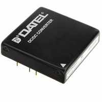
BWR-12/830-D12A-C Murata Power Solutions Inc, BWR-12/830-D12A-C Datasheet - Page 4

BWR-12/830-D12A-C
Manufacturer Part Number
BWR-12/830-D12A-C
Description
CONV DC/DC +/-12V +/-830MA DIP
Manufacturer
Murata Power Solutions Inc
Series
BWRr
Type
Isolatedr
Datasheet
1.BWR-12830-D12A-C.pdf
(6 pages)
Specifications of BWR-12/830-D12A-C
Number Of Outputs
2
Output
±12V
Power (watts)
20W
Mounting Type
Through Hole
Voltage - Input
9 ~ 36V
Package / Case
8-DIP Module (7 Leads)
1st Output
12 VDC @ 830mA
2nd Output
-12 VDC @ 830mA
Size / Dimension
2.00" L x 2.00" W x 0.45" H (50.8mm x 50.8mm x 11.4mm)
Power (watts) - Rated
20W
Operating Temperature
-40°C ~ 100°C
Efficiency
83%
Approvals
CE, cUL, EN, UL
Output Power
10 W
Input Voltage Range
9 V to 36 V
Output Voltage (channel 1)
12 V
Output Current (channel 1)
0.83 A
Output Voltage (channel 2)
- 12 V
Output Current (channel 2)
-0.83 A
Isolation Voltage
1.5 KV
Product
Isolated
Lead Free Status / RoHS Status
Lead free / RoHS Compliant
3rd Output
-
4th Output
-
Lead Free Status / Rohs Status
Lead free / RoHS Compliant
Other names
811-1730-5
Available stocks
Company
Part Number
Manufacturer
Quantity
Price
Company:
Part Number:
BWR-12/830-D12A-C
Manufacturer:
HITTITE
Quantity:
101
Company:
Part Number:
BWR-12/830-D12A-C
Manufacturer:
Murata Power Solutions Inc
Quantity:
135
Input Fusing
Certain applications and/or safety agencies may require the installation of
fuses at the inputs of power conversion components. For MPS A-Series
BWR 15-20 Watt DC/DC Converters, you should use slow-blow type fuses
with values no greater than the following:
On/Off Control
The On/Off Control pin (pin 4) may be used for remote on/off operation. A
TTL logic high (+2 to +5 Volts, 250μA max.) applied to pin 4 disables the
converter. A TTL logic low (0 to +0.8 Volts, 70μA max.), or no connection,
enables the converter. Control voltages should be referenced to pin 2
(–Input). Applying a voltage to the Control pin when no input power is applied
to the converter can cause permanent damage to the converter.
Output Trimming
The total output voltage span, from +Output (pin 5) to –Output (pin 7) may
be trimmed ±5% via a single external trimpot or fixed resistor. The trimpot
should be connected as shown in Figure 3a with its wiper connected to pin 8
(Trim). A trimpot can be used to determine the value of a single fixed resistor
which should be connected as shown in Figures 3b and 3c. Connect the
resistor between pin 8 (Trim) and pin 5 (+Output) to trim "down" the output
voltages. Connect the resistor between pins 8 and 7 (–Output) to trim "up"
the output voltages. Fixed resistors should be metal-film types with absolute
TCR’s less than 100ppm/°C to ensure stability.
C
IN
+
V
D5A
D12A
D48A
IN
Range
Figure 2. Using External Capacitors to Reduce
2
1
+INPUT
–INPUT
Input/Output Ripple/Noise
Fuse Value
6A
4A
2A
+OUTPUT
–OUTPUT
COMMON
www.murata-ps.com
5
6
7
+
+
C
C
OUT
OUT
1 5 - 2 0 W , D u a l O u t p u t D C / D C C o n v e r t e r s
1
2
2
2
1
1
+INPUT
–INPUT
+INPUT
–INPUT
+INPUT
–INPUT
Figure 3a. Trim Connections Using a Trimpot
Figure 3b. Fixed-Value Trim Down Resistor
Technical enquiries email: sales@murata-ps.com, tel:
Figure 3c. Fixed-Value Trim Up Resistor
–OUTPUT
+OUTPUT
COMMON
+OUTPUT
+OUTPUT
COMMON
–OUTPUT
COMMON
–OUTPUT
TRIM
TRIM
TRIM
8
5
7
6
5
6
8
7
5
8
6
7
BWR Models
MDC_BWR15_20_B02 Page 4 of 6
20k
5-10
Turns
LOAD
LOAD
+1 508 339 3000
LOAD
LOAD
LOAD
LOAD


