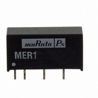
MER1S1209SC Murata Power Solutions Inc, MER1S1209SC Datasheet - Page 3

MER1S1209SC
Manufacturer Part Number
MER1S1209SC
Description
CONV DC/DC 1KVDC TH 1W 12-9V
Manufacturer
Murata Power Solutions Inc
Series
MER1r
Type
Isolatedr
Datasheet
1.MER1S2405SC.pdf
(7 pages)
Specifications of MER1S1209SC
Number Of Outputs
1
Output
9V
Power (watts)
1W
Mounting Type
Through Hole
Voltage - Input
10.8 ~ 13.2V
Package / Case
7-SIP Module (4 Leads)
1st Output
9 VDC @ 111mA
Size / Dimension
0.77" L x 0.24" W x 0.40" H (19.7mm x 6.2mm x 10.2mm)
Power (watts) - Rated
1W
Operating Temperature
-40°C ~ 85°C
Efficiency
86.5%
Approvals
UL
Output Power
1 W
Input Voltage Range
10.8 V to 13.2 V
Input Voltage (nominal)
12 V
Output Voltage (channel 1)
9 V
Output Current (channel 1)
111 mA
Isolation Voltage
1 KV
Product
Isolated
Lead Free Status / RoHS Status
Lead free / RoHS Compliant
3rd Output
-
2nd Output
-
4th Output
-
Lead Free Status / Rohs Status
Lead free / RoHS Compliant
Other names
811-2129-5
Available stocks
Company
Part Number
Manufacturer
Quantity
Price
Company:
Part Number:
MER1S1209SC
Manufacturer:
Murata Power Solutions Inc
Quantity:
135
Company:
Part Number:
MER1S1209SC
Manufacturer:
muRataPs
Quantity:
12 000
APPLICATION NOTES
www.murata-ps.com
Minimum load
The minimum load to meet datasheet specifi cation is 10% of the full rated load across the specifi ed input voltage range. Lower than 10% minimum loading will result in
an increase in output voltage, which may rise to typically double the specifi ed output voltage if the output load falls to less than 5%.
Capacitive loading and start up
Typical start up times for this series, with a typical input voltage rise time of 2.2μs and output capacitance of 10μF, are shown in the table below. The product
series will start into a capacitance of 47μF with an increased start time, however, the maximum recommended output capacitance is 10μF.
Ripple & Noise Characterisation Method
Ripple and noise measurements are performed with the following test confi guration.
Differential Mode Noise Test Schematic
C1
C2
C3
R1
R2
T1
RLOAD
Measured values are multiplied by 10 to obtain the specifi ed values.
MER1S0505SC
MER1S0509SC
MER1S0512SC
MER1S0515SC
MER1S1205SC
MER1S1209SC
MER1S1212SC
MER1S1215SC
MER1S1505SC
MER1S1509SC
1μF X7R m ultilayer ceramic capacitor, voltage rating to be a minimum of 3 times the output voltage of the DC/DC converter
10μF tantalum capacitor, voltage rating to be a minimum of 1.5 times the output voltage of the DC/DC converter with an ESR of less
than 100mΩ at 100 kHz
100nF multilayer ceramic capacitor, general purpose
450Ω resistor, carbon fi lm, ±1% tolerance
50Ω BNC termination
3T of the coax cable through a ferrite toroid
Resistive load to the maximum power rating of the DC/DC converter. Connections should be made via twisted wires
Start-up time
1730
3780
6700
2605
3754
5280
1859
600
750
704
μs
SUPPLY
MER1S1512SC
MER1S1515SC
MER1S2405SC
MER1S2409SC
MER1S2412SC
MER1S2415SC
MER1S4805SC
MER1S4809SC
MER1S4812SC
MER1S4815SC
DC/DC Converter
Input
+
-
Output
+
-
Start-up time
C1 C2 C3
3375
5090
1634
2682
1432
2528
3884
431
245
512
μs
R LOAD
R1
1kVDC Isolated 1W Single Output DC/DC Converters
T1
Technical enquiries email: mk@murata-ps.com, tel: +44 (0)1908 615232
R2
OSCILLOSCOPE
Y INPUT
Typical Start-Up Wave Form
2011/01/24 KDC_MER1.B03 Page 3 of 7
MER1 Series


