LSN2-T/10-W3-C Murata Power Solutions Inc, LSN2-T/10-W3-C Datasheet - Page 4
LSN2-T/10-W3-C
Manufacturer Part Number
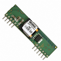
LSN2-T/10-W3-C
Description
CONV DC/DC 33W 10A .75-3.3V SIP
Manufacturer
Murata Power Solutions Inc
Series
LSN2r
Type
Point of Load (POL) Non-Isolatedr
Datasheet
1.LSN2-T10-W3N-C.pdf
(15 pages)
Specifications of LSN2-T/10-W3-C
Number Of Outputs
1
Output
0.75 ~ 3.3V
Power (watts)
33W
Mounting Type
Through Hole
Voltage - Input
2.4 ~ 5.5V
Package / Case
12-SIP Module
1st Output
0.75 ~ 3.3 VDC @ 10A
Size / Dimension
2.00" L x 0.32" W x 0.50" H (50.8mm x 8.1mm x 12.7mm)
Power (watts) - Rated
33W
Operating Temperature
-40°C ~ 85°C
Efficiency
95%
Approvals
CSA, EN, UL
Output Power
33 W
Input Voltage Range
2.4 V to 5.5 V
Output Voltage (channel 1)
0.75 V to 3.3 V
Output Current (channel 1)
10 A
Package / Case Size
SIP
Product
Non-Isolated / POL
Lead Free Status / RoHS Status
Lead free / RoHS Compliant
3rd Output
-
2nd Output
-
Lead Free Status / Rohs Status
Lead free / RoHS Compliant
Other names
811-1798
Available stocks
Company
Part Number
Manufacturer
Quantity
Price

Part Number:
LSN2-T/10-W3-C
Manufacturer:
MURATA/村田
Quantity:
20 000


(1)
(2)
(3)
(4)
(5)
(6)
(7)
(8)
(9)
(10)
(11)
(12)
(13)
(14)
(15)
(16)
(17)
(18)
All models are tested and specifi ed with external 1 || 10μF ceramic/tantalum output capacitors and
a 22μF external input capacitor. All capacitors are low ESR types. These capacitors are necessary
to accommodate our test equipment and may not be required to achieve specifi ed performance in
your applications. All models are stable and regulate within spec under no-load conditions.
General conditions for Specifi cations are +25°C, V
output voltage is +5V for D12 models and +3.3V for W3 models.
Input Back Ripple Current is tested and specifi ed over a 5-20MHz bandwidth. Input fi ltering is
C
Note that Maximum Power Derating curves indicate an average current at nominal input voltage. At
higher temperatures and/or lower airfl ow, the DC/DC converter will tolerate brief full current outputs
if the total RMS current over time does not exceed the derating curve.
Mean Time Before Failure is calculated using the Telcordia (Belcore) SR-332 Method 1, Case 3,
ground fi xed conditions, T
The On/Off Control may be driven with external logic or by applying appropriate external voltages
which are referenced to –Input Common. The On/Off Control Input should use either an open
collector/open drain transistor or logic gate which does not exceed +V
resistor to +V
Short circuit shutdown begins when the output voltage under increasing load degrades approxi-
mately 2% from the selected setting.
If Sense is connected remotely at the load, up to 0.5 Volts difference is allowed between the Sense
and +V
cause the converter to exceed maximum power dissipation.
Output noise may be further reduced by adding an external fi lter. See I/O Filtering and Noise Reduction.
All models are fully operational and meet published specifi cations, including “cold start” at –40°C.
V
Regulation specifi cations describe the deviation as the line input voltage or output load current is
varied from a nominal midpoint value to either extreme.
Other input or output voltage ranges are available under scheduled quantity special order.
Maximum PC board temperature is measured with the sensor in the center.
Do not exceed maximum power specifi cations when adjusting the output trim.
When Sequencing is not used, the Power Good output is TRUE at any time the output is within
approximately ±10% of the voltage set point. Power Good basically indicates if the converter is in
regulation. Power Good detects Over Temperature if the PWM has shut down due to OT. Power
Good does not directly detect Over Current.
If Sequencing is in progress, Power Good will falsely indicate TRUE (valid) before the output
reaches its setpoint. Ignore Power Good if Sequencing is in transition.
The maximum output capacitive loads depend on the the Equivalent Series Resistance (ESR) of
the external output capacitor.
Do not use Pre-bias startup and sequencing together. See Technical Notes below.
After short circuit shutdown, if the load is partially removed such that the load still exceeds the
overcurrent (OC) detection, the converter will remain in hiccup restart mode.
For best noise performance, leave the Track/Sequence pin OPEN when not used.
IN
OUT
= 2 x 100μF tantalum, C
is nominal.
OUT
pins to compensate for ohmic voltage drop in the power lines. A larger voltage drop may
IN
PERFORMANCE/FUNCTIONAL SPECIFICATION NOTES
will cause the “ON” state for negative logic models.
PCBOARD
BUS
= 1000μF electrolytic, L
= +25°C, full output load, natural air convection.
IN
= nominal, V
BUS
= 1μH.
OUT
= nominal, full load. “Nominal”
IN
. A 68K: external pullup
www.murata-ps.com
Soldering Guidelines
Murata Power Solutions recommends the specifi cations below when installing these
converters. These specifi cations vary depending on the solder type. Exceeding these
specifi cations may cause damage to the product. Be cautious when there is high atmo-
spheric humidity. We strongly recommend a mild pre-bake (100° C. for 30 minutes). Your
production environment may differ; therefore please thoroughly review these guidelines
with your process engineers.
For Sn/Ag/Cu based solders:
Maximum Preheat Temperature
Maximum Pot Temperature
Maximum Solder Dwell Time
For Sn/Pb based solders:
Maximum Preheat Temperature
Maximum Pot Temperature
Maximum Solder Dwell Time
Wave Solder Operations for through-hole mounted products (THMT)
Input Voltage (Continuous or transient)
On/Off Control
Input Reverse Polarity Protection
Output Current
Storage Temperature
Lead Temperature
These are stress ratings. Exposure of devices to greater than any of these conditions may
adversely affect long-term reliability. Proper operation under conditions other than those listed in
the Performance/Functional Specifi cations Table is not implied.
W3 models
12V models
(7)
ABSOLUTE MAXIMUM RATINGS
Selectable-Output DC/DC Converters
25 Jun 2010
Non-isolated, DOSA-SIP, 6/10/16A
115° C.
270° C.
7 seconds
105° C.
250° C.
6 seconds
+7 Volts
+15 Volts
–0.3V min. to +V
See Fuse section
Current-limited. Devices can
withstand sustained short circuit
without damage.
–55 to +125°C
See soldering guidelines
LSN2 Series
email: sales@murata-ps.com
MDC_LSN2.B07Δ
IN
max.
Page 4 of 15
Related parts for LSN2-T/10-W3-C
Image
Part Number
Description
Manufacturer
Datasheet
Request
R

Part Number:
Description:
CONV DC/DC 33W 10A .75-3.3V SIP
Manufacturer:
Murata Power Solutions Inc
Datasheet:

Part Number:
Description:
CONV DC/DC 50W 10A 0.75-5V SIP
Manufacturer:
Murata Power Solutions Inc
Datasheet:

Part Number:
Description:
CONV DC/DC 50W 10A 0.75-5V SIP
Manufacturer:
Murata Power Solutions Inc
Datasheet:

Part Number:
Description:
DC/DC Converter
Manufacturer:
Murata Power Solutions Inc
Datasheet:
Part Number:
Description:
DC/DC Converter
Manufacturer:
Murata Power Solutions Inc
Datasheet:
Part Number:
Description:
DC/DC Converter
Manufacturer:
Murata Power Solutions Inc
Datasheet:
Part Number:
Description:
DC/DC Converter
Manufacturer:
Murata Power Solutions Inc
Datasheet:

Part Number:
Description:
DC/DC Converters & Regulators 12Vin 0.8-5Vout 30A 150W Power Good Out
Manufacturer:
Murata Power Solutions Inc
Datasheet:

Part Number:
Description:
DC/DC Converters & Regulators 12Vin 0.8-5Vout 22A 112W NonIso DOSA-SIP
Manufacturer:
Murata Power Solutions Inc
Datasheet:
Part Number:
Description:
DC/DC Converters & Regulators 12Vin 0.8-5Vout 22A 112W Neg polarity
Manufacturer:
Murata Power Solutions Inc
Datasheet:

Part Number:
Description:
Transformers 5Vin 5Vout 200mA 4000Vdc 1:1.33 turn
Manufacturer:
Murata Power Solutions Inc
Datasheet:

Part Number:
Description:
POWER SUPPLY
Manufacturer:
Murata Power Solutions Inc
Datasheet:

Part Number:
Description:
DPM LED MINI 2VDC 3.5DIG LP RED
Manufacturer:
Murata Power Solutions Inc
Datasheet:

Part Number:
Description:
CONV DC/DC 1W 5VIN 5VOUT SIP SGL
Manufacturer:
Murata Power Solutions Inc
Datasheet:

Part Number:
Description:
CONV DC/DC 1W 5VIN 3.3V SIP SGL
Manufacturer:
Murata Power Solutions Inc
Datasheet: