S8VM-10005CD Omron, S8VM-10005CD Datasheet - Page 16
S8VM-10005CD
Manufacturer Part Number
S8VM-10005CD
Description
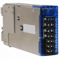
POWER SUPPLY 5V 20A COVERED
Manufacturer
Omron
Series
S8VMr
Specifications of S8VM-10005CD
Voltage - Output
5V
Number Of Outputs
1
Power (watts)
100W
Applications
Commercial
Power Supply Type
Switching (Closed Frame)
Voltage - Input
100 ~ 240VAC
Mounting Type
DIN Rail
1st Output
5 VDC @ 20A
Size / Dimension
6.32" L x 1.3" W x 3.25" H (160.5mm x 33mm x 82.5mm)
Power (watts) - Rated
100W
Operating Temperature
-10°C ~ 60°C
Efficiency
81%
Approvals
CE, CSA, cUL, cUR, EN, TUV, UL
Product
Switching
Output Power Rating
100 W
Input Voltage
100 VAC to 240 VAC
Output Voltage (channel 1)
5 V
Output Current (channel 1)
20 A
Mounting Style
DIN Rail
Dimensions
160.5 mm L x 33 mm W x 82.5 mm H
Open Frame/enclosed
Enclosed
Lead Free Status / RoHS Status
Lead free / RoHS Compliant
3rd Output
-
2nd Output
-
4th Output
-
Lead Free Status / Rohs Status
Lead free / RoHS Compliant
Other names
S8VM10005CD
Z2487
Z2487


■ Remote Control Function
This function turns outputs ON and OFF using an external signal
while input voltage is applied, using the +RC pin (pin 7 on CN) and
the -RC pin (pin 8 on CN). Connect a switch or transistor to the +RC
and -RC pins to use the remote control function. When not using this
function, the +RC and -RC pins are shorted by using the standard
supplied connector.
Maximum input voltage: 12 V max.
Maximum allowable reverse voltage: − 1 V max.
Sink Current: 3.5 mA
Note: 1. Use 2-conductor shielded cable or twisted-pair cable as
■ Power Failure Alarm Function
The power failure alarm indicator will light red to indicate an output
voltage error if overload, overvoltage, or overheat protection is acti-
vated, if a drop in the input voltage causes the output voltage to drop,
if the built-in fan motor stops, and during remote control standby. The
alarm is also output externally by a transistor.
Transistor output: 30 VDC max., 50 mA max.
Residual voltage when ON: 2 V max.
Leakage current when OFF: 0.1 mA max.
Alarm detection voltage: Approx. 80% of output voltage setting
During detection, the transistor is OFF (with no continuity across pins
11 and 12 on CN), and the LED (red) lights.
Note: 1. This function monitors the voltage at the Power Supply out-
16
Short or L (0 to 0.8 V) ON
Open or H (2.4 to 12 V) OFF
+ RC Level for − RC
2. The remote control circuit is isolated from the input and out-
3. Remove the standard supplied connector and prepare a
2. Outputs are forced OFF if the built-in fan motor stops
3. Remove the standard supplied connector and prepare a
connection wire.
put circuits of the power supply.
connector separately.
put terminals. To check actual voltage, measure the voltage
on the load side.
(S8VM-15224C only).
connector separately.
Switch Mode Power Supply
S8VM
S8VM
CN
CN
Output
PF-C
PF-E
+RC
−RC
Vce max.: 30 VDC
Ic max.: 50 mA
SW
Rotate
Stop
Built-in Fan Motor
S8VM
TR
■ Inrush Current, Start Up Time,
■ Input Current Waveform When
(The following examples show typical waveforms.)
S8VM-300@@C
100 VAC, Load ratio: 100%
200 VAC, Load ratio: 100%
AC input
AC input
(10 A/DIV)
(10 A/DIV)
voltage
voltage
current
Output
AC input
AC input
AC input
AC input
voltage
voltage
voltage
voltage
current
current
Output
Output Hold Time
Input Is Turned ON
Output
Input ON
Inrush current on input application
100 ms
100 ms
Start up time
90%
Hold time
Input OFF
95%
Related parts for S8VM-10005CD
Image
Part Number
Description
Manufacturer
Datasheet
Request
R

Part Number:
Description:
POWER SUPPLY, DIN-RAIL, COVERED, 100 WATT, 24 VOLT, 4.5A
Manufacturer:
Omron Automation
Datasheet:
Part Number:
Description:
POWER SUPPLY, DIN-RAIL, COVERED, 100 WATT, 24 VOLT, 4.5A, WITH UNDERVOLTAGE ALARM
Manufacturer:
Omron Automation
Datasheet:
Part Number:
Description:
POWER SUPPLY, DIN-RAIL, COVERED, 100 WATT, 12 VOLT, 8.5A
Manufacturer:
Omron Automation
Datasheet:

Part Number:
Description:
POWER SUPPLY 24V 6.5A COVERED
Manufacturer:
Omron
Datasheet:

Part Number:
Description:
POWER SUPPLY 15V 2A COVERED
Manufacturer:
Omron
Datasheet:
Part Number:
Description:
POWER SUPPLY 24V 1.3A COVERED
Manufacturer:
Omron
Datasheet:

Part Number:
Description:
POWER SUPPLY 5V 6A COVERED
Manufacturer:
Omron
Datasheet:

Part Number:
Description:
POWER SUPPLY 15V 2A COVERED
Manufacturer:
Omron
Datasheet:

Part Number:
Description:
POWER SUPPLY 24V 2.2A COVERED
Manufacturer:
Omron
Datasheet:

Part Number:
Description:
POWER SUPPLY 24V 6.5A COVERED
Manufacturer:
Omron
Datasheet:
Part Number:
Description:
G6S-2GLow Signal Relay
Manufacturer:
Omron Corporation
Datasheet:
Part Number:
Description:
Compact, Low-cost, SSR Switching 5 to 20 A
Manufacturer:
Omron Corporation
Datasheet:
Part Number:
Description:
Manufacturer:
Omron Corporation
Datasheet: