SWT100-522 TDK Corporation, SWT100-522 Datasheet - Page 13
SWT100-522
Manufacturer Part Number
SWT100-522
Description
PWR SUP 100W +5 +12 -12V TRIPLE
Manufacturer
TDK Corporation
Series
SWT100r
Specifications of SWT100-522
Voltage - Output
5V, ±12V
Number Of Outputs
3
Power (watts)
100W
Applications
Commercial
Power Supply Type
Switching (Open Frame)
Voltage - Input
85 ~ 265VAC
Mounting Type
Chassis Mount
1st Output
5 VDC @ 8A
2nd Output
12 VDC @ 4A
3rd Output
-12 VDC @ 800mA
Size / Dimension
7.75" L x 4.25" W x 1.77" H (196.9mm x 108mm x 45mm)
Power (watts) - Rated
100W
Operating Temperature
0°C ~ 50°C
Efficiency
74%
Approvals
CSA, DENAN, EN, UL
Line Regulation
1%, 2%
Load Regulation
2%, 4%
Rohs Compliant
YES
4th Output
-
Lead Free Status / RoHS Status
Other names
285-1065
SWT100522
SWT100522


・All specifications are subject to change without notice.
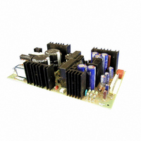
SWT
SWT100 Component Side
Input voltage range of SWT30, SWT40 and SWT100 is si-
ngle phase 85-265VAC (47-63Hz) or DC110-340V.
Input voltage range for SWT65 is 85-132VAC or 170-
265VAC. Do not switch input voltage from 85-132VAC
directly to 170-265VAC, as may cause power supply dam-
aged.
All output voltage are fixed type (CH1, CH2, CH3). It
cannot be adjusted.
The output voltage of all channel is stabilized when more
than minimum output current of CH1 (all model) and CH2
(only SWT30, 40).
OCP circuit with zener diode clamp system is built into CH1
output (+5V). Over 6V of nominal voltage will clamp the
output. If the output voltage is lowered to due to the over-
voltage application, the output will not resume. Replace-
ment of the power supply unit is necessary (for a fee).
OCP type is current limiting with automatic recovery. OCP
function operates when the output current exceeds OCP
specifications. The output automatically recovers when the
over current / shorted conditions is removed. The output
will be automatically recovered whtn the overload or dead
short condition is canceled. When OCP operates in any of
the outputs, the other outputs will also get lowered. Do not
operate in overload or dead short conditions for more than
30 seconds. It could result in damage.
SWT100 Terminal Explanation
Input Voltage Range
Output Voltage Range Adjustment
Minimum Output Current
Over Voltage Protection (OVP)
Over Current Protection (OCP)
SERIES
2. Explanation of Functions and Precautions
Input
Component Side
Output
The standard specification for maximum ripple value is
measured according to measurement circuit specified by
JEITA-RC9131. When load lines are longer, ripple be-
comes larger. In this case, electrolytic capacitor, film ca-
pacitor, etc. might be necessary to use across the load ter-
minal. The output ripple cannot be measured accurately if
the probe ground lead of oscilloscope is too long.
This series uses power thermistor to protect the circuit
from inrush current. Please carefully select input switch
and fuse in cases of the high temperature and the power
re-input.
Output current of CH1(+5V) and CH2(+V) of SWT30, SWT
40 can cope with peak current loads. Specified maximum
output current and peak output current must satisfy formu-
las below. Allowable peak output operating duration is less
than 10 sec. Cycle should be more than 10ms and duty
should be ≦ 0.35. (τ≦10 seconds)
Ip :Peak Output Current
Iav :Average output current
Im :Average output current
τ :Pulse width of peak output current
T
Ripple
Inrush Current
Peak Output Current
OA
OA
aA
① FG(1) terminal (pin 1 of CN1)
FG(2) terminal (faston terminal)
Connect FG(1) or FG(2) to safety ground of appa-
② AC input terminal (pin 4 of CN1)
L: Live line (fuse in line)
③ AC input terminal (pin 6 of CN1)
N: Neutral line
④ Protective earth: Must be connected to electrically
⑤ CH1 +5V output terminal (pin 1-3 of CN2)
⑥ GND CH1, CH2, CH3 common ground terminal
(pin4-6 of CN2)
⑦ CH2 +V output terminal (pin 7 and 8 of CN2)
⑧ CH3 -V output terminal (pin 9 of CN2)
⑨ NC:Non connection
l p
:Period
l p
(Average output current of specification)
ratus or equipment.
safe ground of apparatus or equipment by electri-
cally conductive spacers.
τ
τ
T
T
l m
l m
I
AV
≧Im=
I
AV
≧Im=
(Ip−a)× τ
Ip× τ
T
T
(Sec)
(Sec)
(A)
(A)
(A)
+ a
A-285
Alpha II
DLP
FPS
Genesys
HK-A
HWS
JWS-P
JWT
MTW
RKE
RKY
RTW
SWT
UNA
VS
VS-P
ZUP
ZWD-
PAF
ZWQ
ZWS
ZWS-
PAF
Related parts for SWT100-522
Image
Part Number
Description
Manufacturer
Datasheet
Request
R

Part Number:
Description:
PWR SUP 100W +5 +12 -5V TRIPLE
Manufacturer:
TDK Corporation
Datasheet:
Part Number:
Description:
PWR SUP 100W +5 +15 -15V TRIPLE
Manufacturer:
TDK Corporation
Datasheet:

Part Number:
Description:
TDK DC to DC Converters, DC to AC Inverters
Manufacturer:
TDK Corporation
Datasheet:
Part Number:
Description:
TDK DC to DC Converters, DC to AC Inverters
Manufacturer:
TDK Corporation
Datasheet: