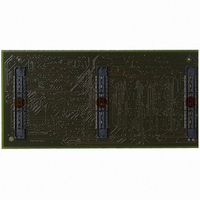
ATICE50MEM Atmel, ATICE50MEM Datasheet - Page 16

ATICE50MEM
Manufacturer Part Number
ATICE50MEM
Description
ICE50 EXTENSION MEMORY CARD
Manufacturer
Atmel
Datasheet
1.ATICE50MEM.pdf
(73 pages)
Specifications of ATICE50MEM
Accessory Type
ICE50 Memory Extension Card
For Use With/related Products
100-pin megaAVR Devices
Lead Free Status / RoHS Status
Contains lead / RoHS non-compliant
- Current page: 16 of 73
- Download datasheet (2Mb)
2523A–AVR–11/02
General Description
3.2
3.2.1
3.2.2
3-2
Main Emulator
Unit
Emulator Unit
Status LEDs
The main emulator unit contains the “brain” of the ICE50.
The main emulator unit is shown in Figure 3-1. The main unit contains the control logic,
and general hardware necessary to emulate an AVR device.
Figure 3-1. ICE50 Main Emulator
There are three LEDs on the front of the ICE50 cabinet. One red, one red/green duo
LED and one green LED. All these LEDs give important status information on the ICE50
and which mode it is operating in. The picture below shows a close-up of the LEDs.
When turning on power on the ICE50 the normal LED sequence will be as follows:
1. Red Power LED turns ON.
2. Mode LED turns ON and is first red and next orange.
3. Green status LED turns ON (after approx 15 seconds).
Figure 3-2. Emulator LEDs
Status LEDs
POD Bay
Expansion Bay
USB Connector
RS-232C Connector
Reset Button
Power Switch
Power Connector
This indicate that the unit is operating and ready for use.
Power Connector/
Power Switch
Expansion Bay
Button
Reset
RS-232C/
USB
LEDs
POD Bay
ICE50 User Guide
Related parts for ATICE50MEM
Image
Part Number
Description
Manufacturer
Datasheet
Request
R

Part Number:
Description:
EMULATOR IN CIRCUIT MEGAAVR
Manufacturer:
Atmel
Datasheet:

Part Number:
Description:
DEV KIT FOR AVR/AVR32
Manufacturer:
Atmel
Datasheet:

Part Number:
Description:
INTERVAL AND WIPE/WASH WIPER CONTROL IC WITH DELAY
Manufacturer:
ATMEL Corporation
Datasheet:

Part Number:
Description:
Low-Voltage Voice-Switched IC for Hands-Free Operation
Manufacturer:
ATMEL Corporation
Datasheet:

Part Number:
Description:
MONOLITHIC INTEGRATED FEATUREPHONE CIRCUIT
Manufacturer:
ATMEL Corporation
Datasheet:

Part Number:
Description:
AM-FM Receiver IC U4255BM-M
Manufacturer:
ATMEL Corporation
Datasheet:

Part Number:
Description:
Monolithic Integrated Feature Phone Circuit
Manufacturer:
ATMEL Corporation
Datasheet:

Part Number:
Description:
Multistandard Video-IF and Quasi Parallel Sound Processing
Manufacturer:
ATMEL Corporation
Datasheet:

Part Number:
Description:
High-performance EE PLD
Manufacturer:
ATMEL Corporation
Datasheet:

Part Number:
Description:
8-bit Flash Microcontroller
Manufacturer:
ATMEL Corporation
Datasheet:

Part Number:
Description:
2-Wire Serial EEPROM
Manufacturer:
ATMEL Corporation
Datasheet:


