TWR-LCD Freescale Semiconductor, TWR-LCD Datasheet
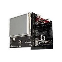
TWR-LCD
Specifications of TWR-LCD


Related parts for TWR-LCD


TWR-LCD Summary of contents
Page 1
... Freescale Semiconductor Inc. TWR‐LCD User’s Manual Rev. 1.0 ...
Page 2
... Contents TWR‐LCD User’s Manual Page 2 of 13 ...
Page 3
... Figure 1 ‐ TWR‐LCD Block Diagram TWR‐LCD User’s Manual Page 3 of 13 ...
Page 4
... Tower documentation. • TWR‐LCD Schematics • TWR‐LCD Quick Start Guide • Truly TFT2N0451‐E LCD Module Specification 3 Hardware Features ...
Page 5
... Enables EBI (8b mode) communication to the LCD Display This interface is only accessible from the Tower Elevator MCU Enables SPI connection from SPI0 of Primary Elevator Connector Enables SPI connection from on-board MCF51JM MCU TWR‐LCD User’s Manual Page 5 of 13 ...
Page 6
... Connects AN4 (TWR-ELEV) to XPLS Touch Panel Signal OFF Disconnects AN4 from Touch Panel ON Connects AN5 (TWR-ELEV) to XMNS Touch Panel Signal OFF Disconnects AN5 from Touch Panel ON Connects AN6 (TWR-ELEV) to YMNS Touch Panel Signal TWR‐LCD User’s Manual Page 6 of 13 ...
Page 7
... OFF Disconnects AN6 from Touch Panel ON Connects AN7 (TWR-ELEV) to YPLS Touch Panel Signal OFF Disconnects AN7 from Touch Panel MicroSD is connected to the SPI1 of Primary Elevator Connector MicroSD is connected to the on-board MCF51JM MCU Group ...
Page 8
... Mass Storage Device. If an appropriate compiled binary (.s19) file is placed in the root directory of the enumerated storage drive, the TWR‐LCD will parse the binary file and reprogram the main application running on the TWR‐LCD. Refer to Section 3.6 for more details. ...
Page 9
... Reset or power cycle to TWR‐LCD to execute the new application. For additional information regarding using and creating the TWR‐LCD Bootloader refer to the TWR‐ LCD Lab Guide Document. TWR‐LCD User’s Manual Page 9 of 13 ...
Page 10
... Touch Panel XPLS B31 GND Ground DAC1 B32 TMR3 B33 TWR‐MEM Primary Connector Used Jmp Pin Name X A1 5V X A2 GND ...
Page 11
... A74 EBI_AD6 A75 EBI_AD5 A76 EBI_AD4 A77 EBI_AD3 TWR‐LCD User’s Manual Usage Used Jmp ...
Page 12
... Connects AN4 of Primary Elevator Connector to XPLS Touch Panel Signal *OFF* Disconnects AN4 from Touch Panel ON Connects AN5 of Primary Elevator Connector to XMNS Touch Panel TWR‐LCD User’s Manual Usage ...
Page 13
... Connects AN7 of Primary Elevator Connector to YPLS Touch Panel Signal *OFF* Disconnects AN7 from Touch Panel are the property of their respective owners. TWR‐LCD User’s Manual Description Page 13 of 13 ...