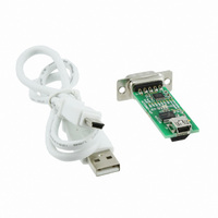
MCP2200EV-VCP Microchip Technology, MCP2200EV-VCP Datasheet - Page 5

MCP2200EV-VCP
Manufacturer Part Number
MCP2200EV-VCP
Description
MOD EVAL USB/RS232 MCP2200
Manufacturer
Microchip Technology
Datasheets
1.MCP2200-IMQ.pdf
(34 pages)
2.MCP2200-IMQ.pdf
(4 pages)
3.MCP2200EV-VCP.pdf
(36 pages)
4.MCP2200EV-VCP.pdf
(20 pages)
Specifications of MCP2200EV-VCP
Design Resources
MCP2200EV-VCP Schematic and PCB
Main Purpose
Interface, USB 2.0 to UART (RS232) Bridge
Embedded
No
Utilized Ic / Part
MCP2200
Primary Attributes
Full Speed (12Mbps)
Secondary Attributes
LED Status Indicators
Processor To Be Evaluated
MCP2200
Processor Series
MCP2200
Interface Type
RS-232, USB
Operating Supply Voltage
3 V to 5.5 V
Silicon Manufacturer
Microchip
Silicon Core Number
MCP2200
Kit Application Type
Interface
Application Sub Type
USB To RS232
Kit Contents
Board, Docs
Tool Type
Demonstration Board
Core Architecture
PIC
Cpu Core
PIC
Data Bus Width
8 bit
Lead Free Status / RoHS Status
Lead free / RoHS Compliant
Lead Free Status / RoHS Status
Lead free / RoHS Compliant, Lead free / RoHS Compliant
Available stocks
Company
Part Number
Manufacturer
Quantity
Price
Company:
Part Number:
MCP2200EV-VCP
Manufacturer:
LT
Quantity:
910
Part Number:
MCP2200EV-VCP
Manufacturer:
MICROCHIP/微芯
Quantity:
20 000
1.3.4
Hardware flow control uses the RTS and CTS pins as
a handshake between two devices. The RTS pin of
one device is typically connected to the CTS of the
other device.
RTS is an active low output which notifies the other
device when it can receive data by driving the pin low.
The MCP2200 trip point for de-asserting RTS (high) is
63 characters. This is one character short of “buffer
full”.
CTS is an active low input which is used to notify the
MCP2200 when it can send data. The MCP2200 will
check CTS just before loading and sending UART data.
If the pin is asserted during a transfer, the transfer will
continue. Refer to
1.3.4.1
The buffer pointer does not increment (or reset to
zero) if the buffer is full. Therefore, if hardware flow
control is not enabled and an overflow occurs (i.e., 65
unprocessed characters received), the new data over-
writes the last position in the buffer.
FIGURE 1-1:
EQUATION 1-1:
2010 Microchip Technology Inc.
I am ready
to receive
I’ll transmit
if okay
Where:
HARDWARE FLOW CONTROL
RTS
MCU
CTS
Flow Control Disabled
ActualRate
x
=
Figure
---------------------------------- -
DesiredBaud
RTS/CTS CONNECTIONS
EXAMPLE
SOLVING FOR ACTUAL
BAUD RATE
12MHz
1-1.
=
12MHz
------------------
int x
MCP2200
RTS
CTS
I am ready
to receive
I’ll transmit
if okay
TABLE 1-3:
1.4
The USB controller in the MCP2200 is full-speed USB
2.0 compliant.
• Composite device (CDC + HID):
• 128 byte buffer to handle data throughput at any
• Fully configurable VID and PID assignments, and
• Bus powered or self-powered
1.4.1
The descriptors are stored in the MCP2200 during
configuration using the supplied PC interface.
1.4.2
The USB Suspend and Resume signals are supported
for power management of the MCP2200. The device
will enter Suspend mode when suspend signaling is
detected on the bus.
The MCP2200 exits the Suspend mode when any of
the following occur:
1.
2.
3.
300
1200
2400
4800
9600
19200
38400
57600
115200
230400
460800
921600
Desired Rate
- CDC: USB-to-UART communications
- HID: I/O control, EEPROM access and initial
UART baud rate:
- 64 byte transmit
- 64 byte receive
descriptors (stored on-chip)
configuration
Resume signaling is detected or generated
A USB Reset signal is detected
A device Reset occurs
USB Protocol Controller
DESCRIPTORS
SUSPEND AND RESUME
UART PRIMARY BAUD
RATES
Actual rate
230769
461538
923077
115385
19200
38339
57692
1200
2400
4800
9600
300
MCP2200
DS22228A-page 5
% Error
0.00%
0.00%
0.00%
0.00%
0.00%
0.00%
0.16%
0.16%
0.16%
0.16%
0.16%
0.16%


