MCP2140DM-TMPSNS Microchip Technology, MCP2140DM-TMPSNS Datasheet - Page 14
MCP2140DM-TMPSNS
Manufacturer Part Number
MCP2140DM-TMPSNS
Description
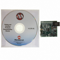
BOARD DEMO FOR MCP2140
Manufacturer
Microchip Technology
Datasheets
1.MCP2140-ISO.pdf
(58 pages)
2.MCP2140-ISO.pdf
(6 pages)
3.MCP2140DM-TMPSNS.pdf
(52 pages)
Specifications of MCP2140DM-TMPSNS
Main Purpose
Interface, IrDA
Embedded
Yes, MCU, 8-Bit
Utilized Ic / Part
MCP2140
Primary Attributes
IrDA Controller with PIC18F MCU and Temp Sensor Temp
Secondary Attributes
Set up as a Data Logger
Processor To Be Evaluated
MCP2140
Interface Type
ICSP
Silicon Manufacturer
Microchip
Silicon Core Number
MCP2140
Kit Application Type
Sensing - Temperature
Application Sub Type
Temperature Sensor
Kit Contents
Board
Rohs Compliant
Yes
Lead Free Status / RoHS Status
Lead free / RoHS Compliant
Lead Free Status / RoHS Status
Lead free / RoHS Compliant, Lead free / RoHS Compliant
Other names
MCP2140DM-TMPSNSR
MCP2140DM-TMPSNSR
MCP2140DM-TMPSNSR
Available stocks
Company
Part Number
Manufacturer
Quantity
Price
Company:

Part Number:
MCP2140DM-TMPSNS
Manufacturer:
Microchip Technology
Quantity:
135
Company:
Part Number:
MCP2140DM-TMPSNS
Manufacturer:
MICROCHIP
Quantity:
12 000


MCP2140
2.8
During IR communication between a Primary Device
and the MCP2140, the MCP2140 is in an operational
mode. In this mode, the MCP2140 consumes the
operational current
For many applications, the time that IR communication
is occurring is a small percentage of the applications
operational time. The ability for the IR controller to be
in a low power mode during this time will save on the
applications power consumption. The MCP2140 will
automatically enter a low power mode once IR activity
has stopped and will return to operational mode once
IR activity is detected on the RXPD and RXPDREF
pins.
Another way to minimize system power is to use an I/O
pin of the Host Controller to enable power to the IR
circuity
DS21790A-page 14
Minimizing Power
(Parameter
D010).
Preliminary
2.8.1
The Automatic Low Power mode allows the system to
achieve the lowest possible operating current.
When the IR link has been “closed”, the protocol han-
dler state machine returns to the Normal Disconnect
Mode (NDM). During NDM, if no IR activity occurs for
about 10 seconds, the device is disabled and enters
into Low Power mode. In this mode, the device oscilla-
tor is shut down and the PHACT pin will be low
(Parameter
Table 2-3
specified in
TABLE 2-3:
2.8.2
The device will exit the Low Power mode when the
RXPD pin voltage crosses the REPDREF pin reference
voltage.
A device reset will also cause the MCP2140 to exit Low
Power mode. After device initialization, if no IR activity
occurs for about 10 seconds, the device is disabled and
returns into the Low Power mode.
2.9
The PHACT signal indicates that the MCP2140 Proto-
col Handler is active. This output pin is an open collec-
tor, so when interfacing to the Host Controller, a pull-up
resistor is required.
PHACT = H
PHACT = L
Note:
Note:
Mode
PHACT Signal
shows the MCP2140 current. These are
Additional system current is from the
Receiver/Transmitter circuitry.
For proper operation, the device oscillator
must be within oscillator specification in
the
Parameter
AUTOMATIC LOW POWER MODE
RETURNING TO DEVICE
OPERATION
D010A).
Parameter D010
Current
2.2 mA
60 µA
DEVICE MAXIMUM
OPERATING CURRENT
time
IR140.
IR communications is
occurring.
No IR communications.
2003 Microchip Technology Inc.
frame
and
Parameter
Comment
specified
D010A.
in
Related parts for MCP2140DM-TMPSNS
Image
Part Number
Description
Manufacturer
Datasheet
Request
R

Part Number:
Description:
IC IRDA CONTROLLR DTE/DCE 18SOIC
Manufacturer:
Microchip Technology
Datasheet:

Part Number:
Description:
The MCP2140 Embeds Irda Protocol Handling And Bit Encoding/decoding, And Provides The Lowest Cost, Lowest Power Consumption Solution For Adding Irda Connectivity to Embedded Systems
Manufacturer:
Microchip Technology, Inc.
Datasheet:

Part Number:
Description:
IC IRDA CONTROLLER DTE/DCE 18DIP
Manufacturer:
Microchip Technology
Datasheet:

Part Number:
Description:
IC IRDA CONTROLLR DTE/DCE 20SSOP
Manufacturer:
Microchip Technology
Datasheet:

Part Number:
Description:
9600 BAUD FIXED SPEED IRDA PROTOCOL HANDLER & BIT ENCODER/DECODER, -40C to +85C, 20-SSOP 208mil, TUBE
Manufacturer:
Microchip Technology
Datasheet:
Part Number:
Description:
IrDA� Standard Protocol Stack Controller With Fixed 9600 Baud Communication Rate
Manufacturer:
MICROCHIP [Microchip Technology]
Datasheet:

Part Number:
Description:
Manufacturer:
Microchip Technology Inc.
Datasheet:
Part Number:
Description:
Manufacturer:
Microchip Technology Inc.
Datasheet:
Part Number:
Description:
Manufacturer:
Microchip Technology Inc.
Datasheet:
Part Number:
Description:
Manufacturer:
Microchip Technology Inc.
Datasheet:
Part Number:
Description:
Manufacturer:
Microchip Technology Inc.
Datasheet:
Part Number:
Description:
Manufacturer:
Microchip Technology Inc.
Datasheet: