MCP7383XEV-DIBC Microchip Technology, MCP7383XEV-DIBC Datasheet - Page 12
MCP7383XEV-DIBC
Manufacturer Part Number
MCP7383XEV-DIBC
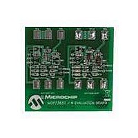
Description
BOARD EVAL FOR MCP73837/8
Manufacturer
Microchip Technology
Type
Battery Managementr
Datasheet
1.MCP7383XEV-DIBC.pdf
(22 pages)
Specifications of MCP7383XEV-DIBC
Main Purpose
Power Management, Battery Charger
Utilized Ic / Part
MCP73837, MCP73838
Product
Power Management Modules
For Use With/related Products
MCP73837, MCP73838
Lead Free Status / RoHS Status
Lead free / RoHS Compliant
Secondary Attributes
-
Embedded
-
Primary Attributes
-
Lead Free Status / Rohs Status
Lead free / RoHS Compliant


MCP73837/8 AC/USB Evaluation Board User’s Guide
2.3
DS51684A-page 8
GETTING STARTED
The MCP73837/8 AC/USB Dual Input Battery Charger Evaluation Board is fully
assembled and tested for charging a single-cell Li-Ion or Li-Polymer battery with a
regulated 5V AC-Adapter or USB-Port.
2.3.1
2.3.1.1
1. Connect the positive battery terminal to V
2. Connect the DC power supply Negative Terminal to GND.
3. Connect the 5V DC power supply Positive Terminal to V
4. Connect the DC power supply Negative Terminal to GND.
5. Connect the 5V DC power supply Positive Terminal to V
6. It should initiate the battery charging cycle when either power source is present.
7. Position the DIP Switch high for maximum up to 500 mA charge rate and low for
8. For MCP73838, TE pull low to enable the internal safety timer while high to
9. Fast Charge Current can be programmed with various resistors that based on
FIGURE 2-1:
Note:
V
Source.
Source.
When both power sources are present, the AC-Adapter Power Source will
provide the input power.
maximum up to 100 mA charging rate. Charging current should be able to read
off multi-meter that is in series with battery.
disable the internal safety timer.
the
BAT-
Figure
.
Power Input and Output Connection
POWERING THE MCP73837/8 AC/USB DUAL INPUT BATTERY
CHARGER EVALUATION BOARD
The battery can be replaced with test circuit or electronic load that can sink
current with DC power supply.
1000
900
800
700
600
500
400
300
200
100
2-1.
0
1
Charge Current (I
3
Programming Resistor (k )
5
7
OUT
) vs. Programming Resistor (R
9
BAT+
1
11
and negative battery terminal to
13
© 2007 Microchip Technology Inc.
AC
USB
for AC-Adapter Power
15
for USB-Port Power
17
PROG
19
).
Related parts for MCP7383XEV-DIBC
Image
Part Number
Description
Manufacturer
Datasheet
Request
R

Part Number:
Description:
Manufacturer:
Microchip Technology Inc.
Datasheet:
Part Number:
Description:
Manufacturer:
Microchip Technology Inc.
Datasheet:
Part Number:
Description:
Manufacturer:
Microchip Technology Inc.
Datasheet:
Part Number:
Description:
Manufacturer:
Microchip Technology Inc.
Datasheet:
Part Number:
Description:
Manufacturer:
Microchip Technology Inc.
Datasheet:
Part Number:
Description:
Manufacturer:
Microchip Technology Inc.
Datasheet:
Part Number:
Description:
Manufacturer:
Microchip Technology Inc.
Datasheet:
Part Number:
Description:
Manufacturer:
Microchip Technology Inc.
Datasheet: