AD5171EVAL Analog Devices Inc, AD5171EVAL Datasheet - Page 18
AD5171EVAL
Manufacturer Part Number
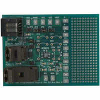
AD5171EVAL
Description
BOARD EVAL FOR AD5171
Manufacturer
Analog Devices Inc
Datasheet
1.AD5171BRJZ10-R7.pdf
(24 pages)
Specifications of AD5171EVAL
Main Purpose
Digital Potentiometer
Utilized Ic / Part
AD5171
Lead Free Status / RoHS Status
Contains lead / RoHS non-compliant
Secondary Attributes
-
Embedded
-
Primary Attributes
-


AD5171
the instruction byte, the last byte in the write mode is the data
byte. Data is transmitted over the serial bus in sequences of nine
clock pulses (eight data bits followed by an acknowledge bit).
The transitions on the SDA line must occur during the low
period of SCL and remain stable during the high period of SCL
(see Figure 35).
In read mode, the data byte follows immediately after the
acknowledgment of the slave address byte. Data is transmitted over
the serial bus in sequences of nine clock pulses (note the slight
difference from the write mode; there are eight data bits followed
by a no acknowledge bit). Similarly, the transitions on the SDA
line must occur during the low period of SCL and remain stable
during the high period of SCL (see Figure 37).
When all data bits are read or written, a stop condition is
established by the master. A stop condition is defined as a low-
to-high transition on the SDA line while SCL is high. In the
write mode, the master pulls the SDA line high during the 10
clock pulse to establish a stop condition (see Figure 35 and
Figure 36). In the read mode, the master issues a no acknowledge
for the 9
master then brings the SDA line low before the 10
which goes high to establish a stop condition (see Figure 37).
th
clock pulse, that is, the SDA line remains high. The
th
clock pulse,
Rev. D | Page 18 of 24
th
A repeated write function gives the user flexibility to update the
RDAC output a number of times, except after permanent
programming, addressing, and instructing the part only once.
During the write cycle, each data byte updates the RDAC output.
For example, after the RDAC has acknowledged its slave address
and instruction bytes, the RDAC output updates after these two
bytes. If another byte is written to the RDAC while it is still
addressed to a specific slave device with the same instruction,
this byte updates the output of the selected slave device. If
different instructions are needed, the write mode has to be
started with a new slave address, instruction, and data bytes.
Similarly, a repeated read function of the RDAC is also allowed.
CONTROLLING TWO DEVICES ON ONE BUS
Figure 38 shows two AD5171 devices on the same serial bus.
Each has a different slave address because the state of each AD0
pin is different, which allows each device to be independently
operated. The master device output bus line drivers are open-
drain pull-downs in a fully I
MASTER
Figure 38. Two AD5171 Devices on One Bus
AD0
AD5171
SDA SCL
2
C-compatible interface.
Rp
5V
Rp
AD0
AD5171
SDA SCL
5V
SDA
SCL
Related parts for AD5171EVAL
Image
Part Number
Description
Manufacturer
Datasheet
Request
R


Part Number:
Description:
Board Mount Temperature Sensors TEMP MONITR DUAL CHN W/SERIES RSTNCE CNCL
Manufacturer:
ON Semiconductor
Datasheet:

Part Number:
Description:
Touch Screen Digitizer
Manufacturer:
Analog Devices, Inc.
Datasheet:
Part Number:
Description:
Half-duplex Icoupler-r Isolated Rs-485 Transceiver
Manufacturer:
Analog Devices, Inc.
Datasheet:

Part Number:
Description:
±1.7g Dual-Axis IMEMS Accelerometer Evaluation Board
Manufacturer:
Analog Devices Inc
Datasheet:

Part Number:
Description:
Inertial Sensor Evaluation System
Manufacturer:
Analog Devices Inc
Datasheet:
Part Number:
Description:
Manufacturer:
Analog Devices Inc
Datasheet:
Part Number:
Description:
Manufacturer:
Analog Devices Inc
Datasheet:
Part Number:
Description:
Manufacturer:
Analog Devices Inc
Datasheet:
Part Number:
Description:
Manufacturer:
Analog Devices Inc
Datasheet:
Part Number:
Description:
Manufacturer:
Analog Devices Inc
Datasheet: