AD5259EVAL Analog Devices Inc, AD5259EVAL Datasheet - Page 16
AD5259EVAL
Manufacturer Part Number
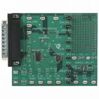
AD5259EVAL
Description
BOARD EVAL FOR AD5259 DGTL POT
Manufacturer
Analog Devices Inc
Datasheet
1.AD5259BRMZ10.pdf
(24 pages)
Specifications of AD5259EVAL
Main Purpose
Digital Potentiometer
Utilized Ic / Part
AD5259
Lead Free Status / RoHS Status
Contains lead / RoHS non-compliant
Secondary Attributes
-
Embedded
-
Primary Attributes
-
Lead Free Status / Rohs Status
Not Compliant


AD5259
I
The following generic, write, read, and store/restore control
registers for the AD5259 all refer to the device addresses listed
in Table 5; the mode/condition reference key (S, P, SA, MA,
NA, W , R, and X) is listed below.
S = Start Condition
P = Stop Condition
SA = Slave Acknowledge
MA = Master Acknowledge
NA = No Acknowledge
W = Write
R = Read
X = Don’t Care
GENERIC INTERFACE
Table 6. Generic Interface Format
S
Table 7. RDAC-to-EEPROM Interface Command Descriptions
C2
0
0
0
1
1
1
1
WRITE MODES
Table 8. Writing to RDAC Register
S
Table 9. Writing to EEPROM Register
S
Table 10. Activating/Deactivating Software Write Protect
S
In order to activate the write protection mode, the WP bit in Table 10 must be logic high. To deactivate the write protection, the
command must be sent again, except with the WP in logic zero state. WP is reset to the deactivated mode if power is cycled off and on.
This command leaves the device in the EEMEM read power state, which consumes power. Issue the NOP command to return the device to its idle state.
2
C-COMPATIBLE FORMAT
7-Bit Device Address
(See Table 5)
Slave Address Byte
7-Bit Device Address
(See Table 5)
Slave Address Byte
7-Bit Device Address
(See Table 5)
Slave Address Byte
7-Bit Device Address
(See Table 5)
Slave Address Byte
C1
0
0
1
0
0
1
C0
0
1
0
0
1
0
Command Description
Operation Between Interface and RDAC.
Operation Between Interface and EEPROM.
Operation Between Interface and Write Protection Register. See Table 10.
NOP.
Restore EEPROM to RDAC.
Store RDAC to EEPROM.
R/W
0
0
0
SA C2 C1 C0 A4 A3 A2 A1 A0 SA D7 D6 D5 D4 D3 D2 D1 D0 SA P
SA 0
SA 0
SA 0
Instruction Byte
Instruction Byte
Instruction Byte
Instruction Byte
1
0
0
1
0
0
1
Rev. B | Page 16 of 24
0
0
0
0
0
0
0
0
0
AD1 and AD0 are two-state address pins.
Table 5. Device Address Lookup
AD1 Address Pin
0
1
0
1
0
0
0
0
0
0
SA D7 D6 D5 D4 D3 D2 D1 D0 SA P
SA D7 D6 D5 D4 D3 D2 D1 D0 SA P
SA 0
Data Byte
Data Byte
Data Byte
Data Byte
AD0 Address Pin
0
0
1
1
0
0
0
0
0
0011000
0011010
1001100
1001110
I
2
C Device Address
0
WP SA P
Related parts for AD5259EVAL
Image
Part Number
Description
Manufacturer
Datasheet
Request
R


Part Number:
Description:
±1.7g Dual-Axis IMEMS Accelerometer Evaluation Board
Manufacturer:
Analog Devices Inc
Datasheet:

Part Number:
Description:
Inertial Sensor Evaluation System
Manufacturer:
Analog Devices Inc
Datasheet:
Part Number:
Description:
Manufacturer:
Analog Devices Inc
Datasheet:
Part Number:
Description:
Manufacturer:
Analog Devices Inc
Datasheet:
Part Number:
Description:
Manufacturer:
Analog Devices Inc
Datasheet:
Part Number:
Description:
Manufacturer:
Analog Devices Inc
Datasheet:
Part Number:
Description:
Manufacturer:
Analog Devices Inc
Datasheet:
Part Number:
Description:
Manufacturer:
Analog Devices Inc
Datasheet:
Part Number:
Description:
Manufacturer:
Analog Devices Inc
Datasheet:
Part Number:
Description:
Manufacturer:
Analog Devices Inc
Datasheet:
Part Number:
Description:
Manufacturer:
Analog Devices Inc
Datasheet:
Part Number:
Description:
Manufacturer:
Analog Devices Inc
Datasheet: