RDK-128 Power Integrations, RDK-128 Datasheet - Page 5
RDK-128
Manufacturer Part Number
RDK-128
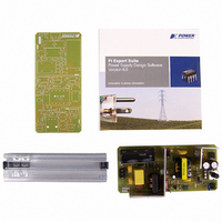
Description
KIT REF DESIGN 36-72W MOTOR DRVR
Manufacturer
Power Integrations
Specifications of RDK-128
Main Purpose
Power Management, Motor Control
Embedded
No
Utilized Ic / Part
PKS606
Primary Attributes
Variable Speed 12V 36W DC Motor, 90 ~ 265 VAC
Secondary Attributes
External Potentiometer or Variable DC Voltage Speed Control
Lead Free Status / RoHS Status
Not applicable / Not applicable
Other names
596-1198


300
the line under-voltage sense circuit prevents a
restart attempt until the AC input voltage is removed
(I
the power MOSFET switching will resume once the AC input
voltage is applied again (I
a latching shutdown function with AC reset during such a fault
condition.
When a brownout or line sag occurs, output regulation may be
lost and the EN/UV pin will receive no feedback (it is pulled
low). A fter 30 ms of no feedback, MOSFET switching is disabled.
Since the AC line is abnormally low (I
switching remains disabled until normal line voltage is restored.
The power MOSFET switching will resume once the AC input
returns to normal (I
latching shutdown function during such a condition.
Auto-Restart (UV resistor not present)
In the event of a fault condition such as output overload,
output short circuit or an open loop condition, PeakSwitch
enters into auto-restart operation. An internal counter
clocked by the oscillator is reset every time the EN/UV pin
is pulled low. When the EN/UV pin receives no feedback
for 30 ms, the power MOSFET switching is disabled for
5 seconds (150 ms for the first auto-restart event). The
auto-restart alternately enables and disables the switching
of the power MOSFET until the fault condition is removed.
Figure 6 illustrates auto-restart circuit operation in the presence
of an output short circuit.
Adaptive Switching Cycle On-time Extension
Adaptive switching cycle on-time extension keeps the MOSFET
on until current limit is reached, instead of terminating after
the DC
because it only occurs after the ENABLE pin has been high
for approximately 750 µs, a condition that would arise if the
200
100
Figure 6. PeakSwitch Auto-Restart Operation.
10
0
5
0
EN
0
<25 µA). Then the internal auto-restart latch is reset and
MAX
signal goes low. This on-time extension is adaptive
V
DC-OUTPUT
V
DRAIN
EN
>25 µA). This effectively disables the
EN
>25 µA). This effectively provides
Time (s)
5
EN
<25 µA) MOSFET
10
Figure 8. PeakSwitch Operation at Moderately Heavy Loading.
peak output power was required in low line conditions. On-time
extension is disabled during the startup of the power supply.
PeakSwitch Operation
PeakSwitch devices operate in the current-limit mode. When
enabled, the oscillator turns the power MOSFET on at the
beginning of each cycle. The MOSFET is turned off when the
current ramps up to the current limit or when the DC
is reached. Since the highest current limit level and frequency
Figure 7. PeakSwitch Operation at Near Maximum Loading.
V
V
I
I
CLOCK
CLOCK
DRAIN
DRAIN
DRAIN
D
D
DRAIN
MAX
MAX
V
V
EN
EN
PKS603-607
PI-2667-090700
PI-2749-050301
MAX
Rev. I 02/07
limit
5
Related parts for RDK-128
Image
Part Number
Description
Manufacturer
Datasheet
Request
R

Part Number:
Description:
KIT REF DESIGN FOR LNK457D
Manufacturer:
Power Integrations
Datasheet:

Part Number:
Description:
REFERENCE DESIGN LINKSWITCH-PH
Manufacturer:
Power Integrations
Datasheet:

Part Number:
Description:
KIT REF DESIGN FOR LNK403EG
Manufacturer:
Power Integrations
Datasheet:

Part Number:
Description:
KIT REF DESIGN FOR LNK406EG
Manufacturer:
Power Integrations
Datasheet:

Part Number:
Description:
KIT REF DESIGN LINKSWITCH-CV
Manufacturer:
Power Integrations
Datasheet:

Part Number:
Description:
KIT REF DESIGN LINKSWITCH 2
Manufacturer:
Power Integrations
Datasheet:

Part Number:
Description:
Specifications: Family: Eval Boards - DC/DC & AC/DC (Off-Line) SMPS ; Series: HiperLCS™ ; Main Purpose: DC/DC, Step Down ; Outputs and Type: 1, Isolated ; Power - Output: 150W ; Voltage - Output: 24V ; Current - Output: 6.25A ; Voltage - Input:
Manufacturer:
Power Integrations, Inc.
Datasheet:

Part Number:
Description:
KIT DESIGN REF TINYSWITCH-III
Manufacturer:
Power Integrations
Datasheet:

Part Number:
Description:
KIT DESIGN REF LINKSWITCH LP
Manufacturer:
Power Integrations
Datasheet:

Part Number:
Description:
KIT REF DESIGN LED LINKSWITCH TN
Manufacturer:
Power Integrations
Datasheet:
Part Number:
Description:
KIT REF DESIGN FOR LNK457D
Manufacturer:
Power Integrations
Datasheet:
Part Number:
Description:
REFERENCE DESIGN LINKSWITCH-PH
Manufacturer:
Power Integrations
Datasheet:
Part Number:
Description:
Specifications: Manufacturer: Power Integrations ; Output Voltage: 380 VDC ; Input / Supply Voltage (Max): 264 VAC ; Input / Supply Voltage (Min): 90 VAC ; Mounting Style: Through Hole ; Output Current: 0.913 A ; Output Power: 347 W
Manufacturer:
Power Integrations, Inc.
Part Number:
Description:
Specifications: Family: Eval Boards - DC/DC & AC/DC (Off-Line) SMPS ; Series: HiperLCS™ ; Main Purpose: DC/DC, Step Down ; Outputs and Type: 1, Isolated ; Power - Output: 150W ; Voltage - Output: 24V ; Current - Output: 6.25A ; Voltage - Input:
Manufacturer:
Power Integrations, Inc.
Datasheet: