CDB42448 Cirrus Logic Inc, CDB42448 Datasheet - Page 51
CDB42448
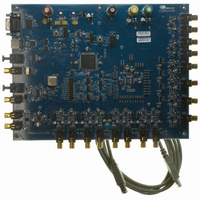
Manufacturer Part Number
CDB42448
Description
BOARD EVAL FOR CS42448 CODEC
Manufacturer
Cirrus Logic Inc
Specifications of CDB42448
Main Purpose
Audio, CODEC
Embedded
Yes, FPGA / CPLD
Utilized Ic / Part
CS42448
Primary Attributes
24-Bit, 192 kHz, 6 ADCs: 102dB Dynamic Range, 8 DACs: 105dB Dynamic Range
Secondary Attributes
Time Division Multiplexed (TDM), I2C, and SPI Interface, Popguard® Technology
Description/function
Audio CODECs
Operating Supply Voltage
5 V to 12 V
Product
Audio Modules
For Use With/related Products
CS42448
Lead Free Status / RoHS Status
Contains lead / RoHS non-compliant
Lead Free Status / RoHS Status
Lead free / RoHS Compliant, Contains lead / RoHS non-compliant
Other names
598-1151


DS648F3
6.13
6.13.1 Interrupt Pin Control (INT[1:0])
6.14
6.14.1 DAC CLOCK ERROR (DAC_CLK ERROR)
6.14.2 ADC CLOCK ERROR (ADC_CLK ERROR)
6.14.3 ADC Overflow (ADCX_OVFL)
Reserved
Reserved
7
7
Status Control (Address 18h)
Status (Address 19h) (Read Only)
For all bits in this register, a “1” means the associated error condition has occurred at least once since the
register was last read. A”0” means the associated error condition has NOT occurred since the last reading
of the register. Reading the register resets all bits to 0. Status bits that are masked off in the associated
mask register will always be “0” in this register.
Default = 00
00 - Active high; high output indicates interrupt condition has occurred
01 - Active low, low output indicates an interrupt condition has occurred
10 - Open drain, active low. Requires an external pull-up resistor on the INT pin.
11 - Reserved
Function:
Determines how the Interrupt pin (INT) will indicate an interrupt condition.
For DAC and ADC clock errors, the INT pin is set to “Level Active Mode” and will become active during
the clock error. For the ADCx_OVFL error, the INT pin is set to Level Active Mode and will become active
during the overflow error.
Default = x
Function:
Indicates an invalid MCLK to DAC_LRCK ratio. This status flag is set to “Level Active Mode” and becomes
active during the error condition. See
Default = x
Function:
Indicates an invalid MCLK to ADC_LRCK ratio. This status flag is set to “Level Active Mode” and becomes
active during the error condition. See
Default = x
Function:
Indicates that there is an over-range condition anywhere in the CS42448 ADC signal path of each of the
associated ADC’s. These status flags become active on the arrival of the error condition.
Reserved
Reserved
6
6
Reserved
Reserved
5
5
DAC_CLK Error
Reserved
4
“System Clocking” on page 30
“System Clocking” on page 30
4
ADC_CLK Error
INT1
3
3
ADC3_OVFL
INT0
2
2
for valid clock ratios.
for valid clock ratios.
ADC2_OVFL
Reserved
1
1
CS42448
ADC1_OVFL
Reserved
0
0
51
Related parts for CDB42448
Image
Part Number
Description
Manufacturer
Datasheet
Request
R

Part Number:
Description:
Development Kit
Manufacturer:
Cirrus Logic Inc
Datasheet:
Part Number:
Description:
Development Kit
Manufacturer:
Cirrus Logic Inc
Datasheet:


Part Number:
Description:
High-efficiency PFC + Fluorescent Lamp Driver Reference Design
Manufacturer:
Cirrus Logic Inc
Datasheet:
Part Number:
Description:
Development Kit
Manufacturer:
Cirrus Logic Inc
Datasheet:
Part Number:
Description:
Development Kit
Manufacturer:
Cirrus Logic Inc
Datasheet:

Part Number:
Description:
Development Kit
Manufacturer:
Cirrus Logic Inc
Datasheet:
Part Number:
Description:
Development Kit
Manufacturer:
Cirrus Logic Inc
Datasheet:
Part Number:
Description:
Development Kit
Manufacturer:
Cirrus Logic Inc
Datasheet:
Part Number:
Description:
Development Kit
Manufacturer:
Cirrus Logic Inc
Datasheet:

Part Number:
Description:
EVALUATION BOARD FOR CS8427
Manufacturer:
Cirrus Logic Inc
Datasheet:

Part Number:
Description:
BOARD EVAL FOR CS8416 RCVR
Manufacturer:
Cirrus Logic Inc
Datasheet:

Part Number:
Description:
EVALUATION BOARD FOR CS8420
Manufacturer:
Cirrus Logic Inc
Datasheet:

Part Number:
Description:
KIT DEVELOPMENT EP9315 ARM9
Manufacturer:
Cirrus Logic Inc
Datasheet:

Part Number:
Description:
KIT DEVELOPMENT EP9302 ARM9
Manufacturer:
Cirrus Logic Inc
Datasheet: