STEVAL-IHT001V1 STMicroelectronics, STEVAL-IHT001V1 Datasheet
STEVAL-IHT001V1
Specifications of STEVAL-IHT001V1


Related parts for STEVAL-IHT001V1


STEVAL-IHT001V1 Summary of contents
Page 1
... Cold Thermostat Kit based on AC switches and ST7LITE MCU Introduction The STEVAL-IHT001V1 Thermostat Kit (figure below) is designed to control a refrigerator or a freezer. This thermostat kit enables the control of a single-phase induction motor, a light bulb and a defrost resistor (or a fan) working on 230 V The board can operate in an ambient temperature range °C. The exact maximum ...
Page 2
... GUI windows description . . . . . . . . . . . . . . . . . . . . . . . . . . . . . . . . . . . . . 16 3.5.1 3.5.2 3.5.3 3.5.4 4 Conclusion . . . . . . . . . . . . . . . . . . . . . . . . . . . . . . . . . . . . . . . . . . . . . . . . 20 Appendix A Thermal sensor linearization . . . . . . . . . . . . . . . . . . . . . . . . . . . . . . 21 Appendix B Wiring connections . . . . . . . . . . . . . . . . . . . . . . . . . . . . . . . . . . . . . . 23 Appendix C STEVAL-IHT001V1 thermostat kit 2/32 Temperature control . . . . . . . . . . . . . . . . . . . . . . . . . . . . . . . . . . . . . . . . . 6 Compressor control . . . . . . . . . . . . . . . . . . . . . . . . . . . . . . . . . . . . . . . . . 7 Light bulb and buzzer operation control . . . . . . . . . . . . . . . . . . . . . . . . . . 7 Defrost resistor (or fan) control . . . . . . . . . . . . . . . . . . . . . . . . . . . . . . . . 7 ACS and ACST devices . . . . . . . . . . . . . . . . . . . . . . . . . . . . . . . . . . . . . . 8 ST7LITE39F2 microcontroller . . . . . . . . . . . . . . . . . . . . . . . . . . . . . . . . . 9 Capacitive power supply . . . . . . . . . . . . . . . . . . . . . . . . . . . . . . . . . . . . . 9 Using the GUI software ...
Page 3
UM0277 Appendix D Bill of materials . . . . . . . . . . . . . . . . . . . . . . . . . . . . . . . . . . ...
Page 4
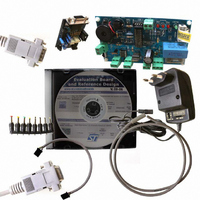
... Kit introduction 1.1 Package contents This package (Figure ● A thermostat board (ref.: STEVAL-IHT001V1) ● A M2020 5k NTC thermistor from EPCOS (ref.: M2020/5k/A17) ● A CD-ROM, including products presentations and data-sheets, user manual, Application Notes and the GUI software. ● “Getting Started” User Manual (this document) ● ...
Page 5
... UM0277 1.2 Board presentation Figure 2 shows the STEVAL-IHT001V1 board and the main components used on this board. Figure 2. Power board (top view ito ito ito This board mainly embeds (refer to ● A capacitor power supply. The average output current of the capacitor power supply is approximately 25 mA with he embedded 1µ ...
Page 6
... The NTC resistance value decreases, following an exponential variation, when the temperature increases. Then, to get back the temperature data, the MCU could use a numerical table. In the STEVAL-IHT001V1 board, a simple resistor has been added in series with the NTC in order to linearize its thermal response (refer to advantages come from this choice: ● ...
Page 7
... A PTC thermal resistor is used to switch off this winding after start-up. In the STEVAL-IHT001V1 thermostat kit, this PTC is not replaced by a TRIAC as proposed on our previous THERM01EVAL kit (refer to AN1354) ...
Page 8
... Hardware features 2.3.1 ACS and ACST devices The STEVAL-IHT001V1 board embeds one ACS102-6TA, one ACS110-7SB2 and one ACST6-7ST switches. The datasheet of these devices can be found in our web site (go to www.st.com/thyristors). switches and traditional TRIACs. Table 1. ...
Page 9
UM0277 2.3.2 ST7LITE39F2 microcontroller The MCU used in the thermostat kit is the ST7LITE39F2. It belongs to the ST7LITE39F2 MCU family. It embeds a large number of features at the minimum cost. The peripheral hardware requirements are then reduced to ...
Page 10
... Moreover, the typical and minimal (nominal capacitor value -10%, minimum RMS line voltage) output DC current capabilities are given for information. One particularity of the STEVAL-ITH001V1 board power supply “negative” one. Indeed, the V terminal is connected to Neutral. This means that the GND voltage below Neutral ...
Page 11
UM0277 3 Getting started 3.1 Load power Initially, there is no heat sink mounted on the TO220-AB of the ACST6-7ST device. In this case, Figure 2.1 of their datasheet shows that the maximum permanent allowed current is 1.5 A RMS, ...
Page 12
Getting started Table 4. Measurement points Footprint Name L N VDD GND ZVS NTC- RUN LIGHT DEFROST 3.3 Pulse control All loads are controlled in full cycle mode by a pulsed gate current. The MCU senses both the mains rising ...
Page 13
... The Kit is not electrically isolated from the AC input. The MCU is directly linked to the mains voltage. No insulation is ensured between the accessible parts and the high voltage. The STEVAL-IHT001V1 Kit must be used with care and only by persons qualified for working with electricity at mains voltage levels. All measurement equipment must be isolated from the mains before powering the board ...
Page 14
... Getting started 3.4.1 Using the GUI software In order to use the GUI of our STEVAL-IHT001V1 kit, a recent version of Windows®, such as Windows 98, Windows 2000 or Windows XP must be installed on your computer. The version of the Windows OS installed on your PC may be checked by clicking on the “System” icon on the Control Panel. ...
Page 15
UM0277 Figure 8. Interface board Perform the following start-up procedure for the GUI: 1. Connect the insulated PC interface board to the PC via the RS232 Interface cable and to the thermostat board via the SCI Interface wire. 2. Connect ...
Page 16
Getting started Figure 9. 230V/9V insulated power supply configuration 3.5 GUI windows description 3.5.1 Temperature control Use the “Thermostat Order” switch position on the GUI push button on the board to select the correct temperature order. Note: ● If “Thermostat ...
Page 17
UM0277 Figure 10. Temperature control tab 3.5.2 Timing control The Timing Control tab to switch ON the TRIACs Q1 (for compressor), the ZVS delay, the delay to activate defrost and the defrost duration. Note that the initial parameters are given ...
Page 18
Getting started measured to switch ON the TRIACs which controls the Light Bulb and the Defrost resistor is approximately 130µs for the AC mains negative cycle (230 V delay measured to switch ON the compressor is approximately 170µs for the ...
Page 19
UM0277 Figure 13. Force debug tab 3.5.4 Parameter measurements The GUI can detect and display all the various parameters of the MCU, such as the temperature order, the evaporator temperature, the AC load states, the compressor cycle information (running period ...
Page 20
... Conclusion 4 Conclusion This document will help cold-appliance designers to use our STEVAL-IHT001V1 thermostat kit to: ● Check the immunity of this ST solution ● Easily check the efficiency gains by hysteresis threshold reduction ● Define the better management of the defrost cycles to improve the overall efficiency ● ...
Page 21
UM0277 Appendix A Thermal sensor linearization An NTC thermistor is a thermal resistor whose value decreases when its temperature increases. The thermal law is exponential, as presented in Equation 1 To achieve a simple voltage sensor better to ...
Page 22
Thermal sensor linearization Figure 14. Linear voltage response of the NTC thermistor (for a 5V supply) 22/32 UM0277 ...
Page 23
UM0277 Appendix B Wiring connections For the NTC thermistor, you just have to connect its terminals to the “NTC” connector. Its wires can be connected in any way just a resistor. The same procedure can be achieved ...
Page 24
... STEVAL-IHT001V1 thermostat kit Appendix C STEVAL-IHT001V1 thermostat kit Figure 17. STEVAL-IHT001V1 evaluation board schematic diagram 24/32 OSCI/CLKIN VDD RST UM0277 ...
Page 25
UM0277 Appendix D Bill of materials Table 5. Bill of materials Name Resistor 150 Ohm-1/ Resistor 130 Ohm-1/ Resistor 390 Ohm-1/ Resistor 150 kOhm-1/ ...
Page 26
Bill of materials Table 5. Bill of materials (continued) Name D1 D2 Led1 Led2 Led3 Led4 Female connector HE10 - 2x5 J10 Centerline-AMPMODU Headers J11 J12 J13 U1 N N/A Q3 TP1 TP2 ...
Page 27
UM0277 Table 5. Bill of materials (continued) Name J6/J7/J8/J9 J6/J7/J8/J9 Fuse N/A N/A Designation STRAP STRAP STRAP Corner Spacer: Screw Corner Spacer: Nut Fuse 5x20mm 8A 250V Fuse socket Socket hood Bill of materials Comment Length is ...
Page 28
Procedure to apply IEC 61000-4-4 bursts test Appendix E Procedure to apply IEC 61000-4-4 bursts test To perform fast transient voltage tests in compliance with EN61000-4-4 specifications on thermostat boards connected to a compressor, a 15W light bulb and a ...
Page 29
UM0277 Appendix F PC interface parameters description Table 6. PC interface parameters description Parameter Temperature Hysteresis Thermostat order Evaporator temperature order 1 Evaporator temperature order 2 Evaporator temperature order 3 Forced Defrost Control Forced Compressor Control Forced Bulb Control Forced ...
Page 30
Capacitor value according to country Appendix G Capacitor value according to country Table 7 indicates the capacitor value for a 30mA average current for typical application case (nominal capacitor value, nominal RMS line voltage) versus different AC mains and frequency ...
Page 31
UM0277 Revision history Table 8. Document revision history Date 28-Aug-2006 Revision 1 Initial release. Revision history Changes 31/32 ...
Page 32
... Information in this document is provided solely in connection with ST products. STMicroelectronics NV and its subsidiaries (“ST”) reserve the right to make changes, corrections, modifications or improvements, to this document, and the products and services described herein at any time, without notice. All ST products are sold pursuant to ST’s terms and conditions of sale. ...