CRD3511-Q1 Cirrus Logic Inc, CRD3511-Q1 Datasheet
CRD3511-Q1
Specifications of CRD3511-Q1


Related parts for CRD3511-Q1


CRD3511-Q1 Summary of contents
Page 1
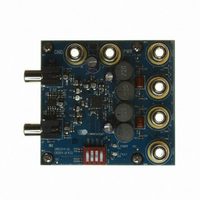
... DIP Switch Input 2 Controls http://www.cirrus.com Description The CRD3511-Q1 demonstrates the CS3511 high-effi- ciency Class-D amplifier. This reference design implements a two-channel amplifier that delivers 9 W per full-bridge channel into 8 Ω loads using a single +12 V supply. Standard RCA phono jacks are provided to easily inter- face single-ended analog input signals with the evaluation board ...
Page 2
... CRD SCHEMATIC .................................................................................................................................. 6 5. CRD LAYOUT ......................................................................................................................................... 7 6. PERFORMANCE PLOTS ..................................................................................................................... 10 7. THERMAL DE-RATING ........................................................................................................................ 13 8. REVISION HISTORY ............................................................................................................................ 14 LIST OF FIGURES Figure 1.CRD3511-Q1 Schematic .............................................................................................................. 6 Figure 2.Component Map ........................................................................................................................... 7 Figure 3.Top-Side Copper Layer ................................................................................................................. 7 Figure 4.Inner Copper Layer 1 .................................................................................................................... 8 Figure 5.Inner Copper Layer 2 .................................................................................................................... 8 Figure 6.Bottom-Side Copper Layer ........................................................................................................... 9 Figure 7.THD+N vs. Output Power (RL .......................................................................................... 10 Figure 8 ...
Page 3
... SYSTEM OVERVIEW The CRD3511-Q1 reference design is an excellent means for evaluating the CS3511 class-D amplifier with integrated protection circuits. A single-ended stereo analog input signal interface is provided; on-board control switches are used for easy modification of the CS3511’s configuration pins. The CRD3511-Q1 schematic is shown in 1 ...
Page 4
... CS3511 Configuration The CRD3511-Q1 is controlled through the settings on switch S1. The switch can toggle the mute, sleep, and gain settings of the CS3511. See Note: The MUTE switch should be set to HIGH (mute enabled) before powering on or off the CRD3511 eliminate audible transients ...
Page 5
... Input Analog input to CS3511. Analog output from CS3511. Table 1. System Connections Low = Mute disabled High = Mute enabled Low = Sleep disabled High = Sleep enabled [Low:Low] = Invalid gain setting [Low:High] = Gain is 21.6 dB [High:Low] = Gain [High:High] = Gain is 29.5 dB Table 2. S1 Settings CRD3511-Q1 Function Selected 5 ...
Page 6
... CRD3511-Q1 DS845RD2 ...
Page 7
... CRD LAYOUT 2.765'' DS845RD2 2.95'' Figure 2. Component Map Figure 3. Top-Side Copper Layer CRD3511-Q1 7 ...
Page 8
... Figure 4. Inner Copper Layer 1 VP 5VGEN Figure 5. Inner Copper Layer 2 CRD3511-Q1 DS845RD2 ...
Page 9
... DS845RD2 Figure 6. Bottom-Side Copper Layer CRD3511-Q1 9 ...
Page 10
... Figure 10. THD+N vs. Frequency (R L 100 Ω) Figure 12. Efficiency vs. Output Power (R L CRD3511-Q1 50m 100m 200m 500m Ω 100 200 500 10k Ω Output Power Per Channel (Watts) L DS845RD2 20 40 ...
Page 11
... B -100 -110 -120 -130 -140 10k 20k = 8 Ω) Figure 16. Crosstalk vs. Frequency ( 10k 20k = 8 Ω Figure 18. Frequency Response (P OUT L CRD3511- Total Output Power (Watts Ω) (R OUT 100 200 500 Ω 100 200 500 10k OUT 20 10k 20k 20k = 6 Ω) ...
Page 12
... Figure 20. Dynamic Range FFT ( -10 -20 -30 -40 -50 -60 d -70 B -80 r -90 A -100 -110 -120 -130 -140 -150 -160 5k 10k 30k Ω Figure 22. Intermodulation FFT (P OUT L CRD3511-Q1 50 100 200 500 10k Ω 100 200 500 10k OUT DS845RD2 20k 30k = 6 Ω) L ...
Page 13
... Because the transfer of heat is less effective at greater ambient temperatures, the amplifier’s maximum sustainable output will be related to the ambient temperature. The CRD3511- four-layer PCB with 1 oz. (0.036 mm thick) copper designed to minimize the thermal resistance from the CS3511 to the ambient air. This optimum board configuration and layout allows the CS3511 to produce and sustain its rated 11 W per channel output power in ambient temperatures as high as 65° ...
Page 14
... TORNEYS’ FEES AND COSTS, THAT MAY RESULT FROM OR ARISE IN CONNECTION WITH THESE USES. Cirrus Logic, Cirrus, and the Cirrus Logic logo designs are trademarks of Cirrus Logic, Inc. All other brand and product names in this document may be trademarks or service marks of their respective owners. 14 Changes 5. www.cirrus.com. CRD3511-Q1 filter description. 3. Section 1.1 on page 3, and in Section DS845RD2 ...