STEVAL-CCA021V1 STMicroelectronics, STEVAL-CCA021V1 Datasheet
STEVAL-CCA021V1
Specifications of STEVAL-CCA021V1


Related parts for STEVAL-CCA021V1


STEVAL-CCA021V1 Summary of contents
Page 1
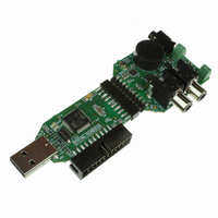
... STMicroelectronics low-voltage audio components in Human machine interface (HMI) audio input/output, portable audio equipment, and simple PC USB demonstration kit applications. Figure 1. STM32F103 USB demonstration kit - top view August 2009 Getting started with STEVAL-CCA021V1, STM32 performance line USB demonstration kit Doc ID 15867 Rev 1 UM0722 User manual 1/46 www ...
Page 2
Contents Contents 1 Introduction . . . . . . . . . . . . . . . . . . . . . . . . . . . . . . . . . . . . ...
Page 3
UM0722 9.5 Microphone functionality . . . . . . . . . . . . . . . . . . . . . . . . . . . . . . . . . . . . ...
Page 4
List of tables List of tables 2 Table audio connector pins description of the STM32 controller board . . . . . . . . . . . . . . . . . 15 Table 2. ...
Page 5
UM0722 List of figures Figure 1. STM32F103 USB demonstration kit - top view . . . . . . . . . . . . . . . . . . . . . . . . . . . ...
Page 6
... Description 2 Description The STM32 performance line USB demonstration kit is designed to demonstrate several STMicroelectronics products: ● The TS4657 is a stereo DAC that integrates a high-performance audio line driver capable of generating a 2.2 V single supply is sufficient for the digital and analog parts of the circuit, thus eliminating the need for external regulators ...
Page 7
UM0722 3 Boards key features STM32 performance line controller board ● STM32F103 performance line microcontroller ● 16 MHz crystal unit ● USB connector and ESD protection ● Two LEDs driven by the microcontroller ● Push button to control the firmware ...
Page 8
General system description 4 General system description The STM32F103 USB demonstration kit consists of two boards. The STM32F103 controller board receives the audio data through USB from PC and transfers them into the I stream in the PCM16 format suitable ...
Page 9
UM0722 5 Getting started 5.1 System requirements In order to use the STM32 performance line USB demonstration kit with the Microsoft ® Windows operating system, a recent version of Windows, such as Windows XP, Windows 98, Windows Millennium or Windows ...
Page 10
Getting started Warning: Figure 3. Device manager window - new USB audio device 10/46 Do not place the STM32 performance line USB demonstration kit speaker close to your ears. It might harm your hearing if the card is set to ...
Page 11
UM0722 6 Boards layout 6.1 STM32 controller board layout Figure 4. STM32 controller board layout 6.2 TS4657 audio card layout Figure 5. TS4657 audio card board layout Doc ID 15867 Rev 1 Boards layout 11/46 ...
Page 12
System setup 7 System setup STM32 performance line USB demonstration kit can be used in two application software modes together with at least five audio input / output connection schemes. This chapter gives a brief description of all possible audio ...
Page 13
UM0722 Figure 7. External mono speaker or headphone system setup 7.1.3 External amplified stereo output configuration To change the audio output from the default onboard speaker to the TS2012 power output, briefly press the B1 button on the controller board. ...
Page 14
System setup In this mode the STM32 performance line USB demonstration kit records 5 s long audio sample and than plays it back through any mean (speaker) presented in the above chapter. In this mode, LD2 blinks at a fast ...
Page 15
UM0722 8 Connectors of the STM32 performance line controller board 2 8 audio connector P2 The P2 connector is used to interconnect the STM32F103 controller board and the TS4657 audio card. This connector is functionally compatible with the ...
Page 16
Connectors of the STM32 performance line controller board choice of development tools on the market supporting microcontroller Flash memory programming and application debugging. Figure 12. JTAG connector Table 2. JTAG connector pins description Pin Signal Pin 1 3V3 DC 2 ...
Page 17
UM0722 9 Connectors and functionality of the TS4657 audio card 2 9 audio connector P1 The P1 connector is used to interconnect the STM32F103 controller board and the TS4657 audio card. This connector is functionally compatible with the ...
Page 18
Connectors and functionality of the TS4657 audio card connector if an external speaker is connected. The output is never available to J4 and U6 at the same time because the mono jack connector J4 has the pin disconnection capability. l ...
Page 19
UM0722 Figure 16. TS2012 stereo output terminal connectors P2 Gain L IN– 17 select Gain R IN – 19 select STBY L 7 Standby ...
Page 20
Connectors and functionality of the TS4657 audio card Figure 17. TS4657 stereo DAC output audio RCA connectors J1 CCA V CCD NCP PCP LRCLK 3 SDAT 4 Digital audio BCLK 5 interface MCLK 6 7 FMT2 Control interface ...
Page 21
UM0722 Figure 18. Microphone functionality C27 1 µF GNDA R11 1 KΩ C19 U5 2 C20 1 100 nF 100 nF KEEG1542PBL R12 1 KΩ GNDA ST: TS472IQT 9.6 TS4657 stereo audio DAC functionality The TS4657 is a stereo digital ...
Page 22
Connectors and functionality of the TS4657 audio card Figure 19. TS4657 stereo audio DAC functionality LRCLK DAC_LRCLK 3 SDAT DAC_SDAT 4 BCLK DAC_BCLK 5 interface MCLK DAC_MCLK 6 FMT2 DAC_FMT2 7 FMT1 Control interface DAC_FMT1 KΩ ...
Page 23
UM0722 Figure 20. TS4962 mono Class-D amplifier functionality GND Mono Class-D amplifier R13 10 KΩ SPK_STBY 1 Input from the TS4657 C21 R14 left channel 150 kΩ 3 100 nF C22 R16 4 150 kΩ 100 nF GND 5 V ...
Page 24
Connectors and functionality of the TS4657 audio card Figure 21. TS2012 stereo Class-D amplifier functionality GND GND Gain control KΩ 10 KΩ C11 – 17 220 nF Input ...
Page 25
UM0722 10 LEDs and buttons 10.1 LED indicators on the STM32 controller board The green LED (LD2) indicates that the demonstration kit is in operating mode. When it is switched on continuously, the PC USB demonstration kit is active; when ...
Page 26
... The same USB connector can be used for both the standard operating mode and the reprogramming process. This operation is made possible by the IAP capability featured by most of the STMicroelectronics USB Flash microcontrollers, which allows a Flash MCU to be reprogrammed by any communication channel. The DFU process, like any other IAP process, is based on the execution of firmware located in one small part of the Flash memory ...
Page 27
UM0722 function. All requests that are concerned with the manipulation of certain audio controls within the audio function's units or terminals must be directed to the AudioControl interface of the audio function. Likewise, all descriptors related to the internals of ...
Page 28
Demonstration kit software General characteristics ● USB-FS-device characteristics: – Endpoint 0: used to enumerate the device and to respond to class-specific requests. The maximum packet size of this endpoint is 64 bytes. – Endpoint 1 (OUT): used to receive the ...
Page 29
... Once the device is in the DFU mode, you can simply update main application with support of tools coming from STM in DfuSe package. For further information, please refer to UM0412 “Getting started with DfuSe USB device firmware upgrade STMicroelectronics extension” user manual, available online from: www.st.com/mcu. ...
Page 30
Test measurement of the audio signal 12 Test measurement of the audio signal Figure 22. Typical Figure 23. TS4657 output versus the I 30/ waveform Transmission Reception 16-bit MSB Channel left 2 S input ...
Page 31
UM0722 Figure 24. TS4657 output versus the I Figure 25. Typical output from the Class-D amplifiers Test measurement of the audio signal 2 S input (10 kHz signal reconstruction) - detail Doc ID 15867 Rev 1 31/46 ...
Page 32
Addendum 13 Addendum Appendix A STM32F103 controller board - BOM Table 7. Bill of material Description Comment Designator Button DT2112C B1 Polarized 4.7 µF C1 capacitor Polarized 4.7 µF C5 capacitor Capacitor 1 µF C2, C3 Capacitor ...
Page 33
... GM Electronic 0603 1 GM Electronic 0603 1 GM Electronic 0603 1 GM Electronic 0603 1 GM Electronic LQFP64_N 1 STMicroelectronics SOT23-5L 1 STMicroelectronics VDFPN8(8*6) 1 STMicroelectronics SOT-666 1 STMicroelectronics TSX-3225_FA- 1 EPSON 238 [0603] 9 Farnell (Kemet) [0603 Electronic [0603 Electronic [0603 Electronic [0603 Electronic C3225[1210 Electronic Doc ID 15867 Rev 1 ...
Page 34
... MPT 0,5/ 2-2,54 2 (PHOENIX CONTACT) [0603 Electronic [0603 Electronic [0603 Electronic [0603 Electronic [0603 Electronic [0603 Electronic [0603 Electronic QFN20_TS4657 1 STMicroelectronics Doc ID 15867 Rev 1 UM0722 Supplier order Note code 901-396 960-023 1200146 1243243 1515716 832-023 3041359 901-399 901-529 901-500 901-498 901-502 901-633 ...
Page 35
... Low noise microphone ST: TS472IQT U4 preamplifier Microphone KEEG1542PBL U5 Transducer, KSSG1708 U6 speaker STM32F103 controller board - BOM Footprint Qty Supplier name QFN20 - TS2012 1 STMicroelectronics DFN8 - TS4962 1 STMicroelectronics QFN24_TS472 1 STMicroelectronics KEC2740 1 Farnell (KINGSTATE) 1502746 KSS1708 1 Farnell (KINGSTATE) 1502738 Doc ID 15867 Rev 1 Supplier order Note code ...
Page 36
STM32F103 controller board Appendix B STM32F103 controller board Figure 26. STM32F103 controller board - top overlay Figure 27. STM32F103 controller board - bottom overlay 36/46 Doc ID 15867 Rev 1 UM0722 ...
Page 37
UM0722 Figure 28. TS4657 audio card - top layer Figure 29. TS4657 audio card - bottom layer Doc ID 15867 Rev 1 STM32F103 controller board 37/46 ...
Page 38
TS4657 audio card - artwork prints Appendix C TS4657 audio card - artwork prints Figure 30. TS4657 audio card - top overlay Figure 31. TS4657 audio card - bottom overlay 38/46 Doc ID 15867 Rev 1 UM0722 ...
Page 39
UM0722 Figure 32. TS4657 audio card - top layer Figure 33. TS4657 audio card - bottom layer TS4657 audio card - artwork prints Doc ID 15867 Rev 1 39/46 ...
Page 40
STM32F103 controller board - schematic Appendix D STM32F103 controller board - schematic Figure 34. STM32F103 controller board - schematic - part 1 40/46 Doc ID 15867 Rev 1 UM0722 ...
Page 41
UM0722 Figure 35. STM32F103 controller board - schematic - part 2 STM32F103 controller board - schematic Doc ID 15867 Rev 1 41/46 ...
Page 42
TS4657 audio card - schematic Appendix E TS4657 audio card - schematic Figure 36. TS4657 audio card - schematic - part 1 42/46 Doc ID 15867 Rev 1 UM0722 ...
Page 43
UM0722 Figure 37. TS4657 audio card - schematic - part 2 TS4657 audio card - schematic Doc ID 15867 Rev 1 43/46 ...
Page 44
TS4657 audio card - schematic Figure 38. TS4657 audio card - schematic - part 3 44/46 Doc ID 15867 Rev 1 UM0722 ...
Page 45
UM0722 Revision history Table 8. Docsument revision history Date 27-Aug-2009 Revision 1 Initial release. Doc ID 15867 Rev 1 Revision history Changes 45/46 ...
Page 46
... Information in this document is provided solely in connection with ST products. STMicroelectronics NV and its subsidiaries (“ST”) reserve the right to make changes, corrections, modifications or improvements, to this document, and the products and services described herein at any time, without notice. All ST products are sold pursuant to ST’s terms and conditions of sale. ...