RDK-142 Power Integrations, RDK-142 Datasheet
RDK-142
Specifications of RDK-142


Related parts for RDK-142


RDK-142 Summary of contents
Page 1
... The products and applications illustrated herein (including circuits external to the products and transformer construction) may be covered by one or more U.S. and foreign patents or potentially by pending U.S. and foreign patent applications assigned to Power Integrations. A complete list of Power Integrations’ patents may be found at www.powerint.com. ...
Page 2
... Ripple Measurement Technique ................................................................33 11.6.2 Measurement Results ................................................................................34 12 Line Surge.............................................................................................................35 13 Control Loop Measurements.................................................................................36 13.1 90 VAC Maximum Load.....................................................................................36 13.2 265 VAC Maximum Load...................................................................................36 14 Conducted EMI .....................................................................................................37 15 Revision History ....................................................................................................38 Power Integrations Tel: +1 408 414 9200 Fax: +1 408 414 9201 www.powerint.com Page ...
Page 3
... Although this board is designed to satisfy safety isolation requirements, the engineering prototype has not been agency approved. Therefore, all testing should be performed using an isolation transformer to provide the AC input to the prototype board. Page Power Integrations Tel: +1 408 414 9200 Fax: +1 408 414 9201 www.powerint.com ...
Page 4
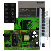
... The document contains the power supply specification, schematic, bill of materials, transformer documentation, printed circuit layout, and performance data. Figure 1 – Populated Circuit Board Photograph (5”L x 2.84”W x 1.16”H). Power Integrations Tel: +1 408 414 9200 Fax: +1 408 414 9201 www.powerint.com Page ...
Page 5
... Per California Energy Commission % (CEC) / Energy Star requirements 1.2/50 µs surge, IEC 1000-4-5, Series Impedance: kV Differential Mode: 2 Ω kV Common Mode: 12 Ω 100 kHz ring wave, 500 A Short kV Circuit Current, Differential and Common Mode o C Free Convection, Sea Level Power Integrations www.powerint.com ...
Page 6
... Schematic Power Integrations Tel: +1 408 414 9200 Fax: +1 408 414 9201 www.powerint.com * * Optional for 2 wire input, floating output Figure 2 – Schematic. Page ...
Page 7
... The internal current limit provides cycle-by-cycle peak current limit protection. TOPSwitch-HX controller has a second current limit comparator allowing monitoring the actual peak drain current (I Page relative to the programmed current limit I P Tel: +1 408 414 9200 Fax: +1 408 414 9201 The . As soon LIMITEXT Power Integrations www.powerint.com ...
Page 8
... Output rectification for the 5 V output is provided by diode D8. Low ESR capacitor C17 provides filtering. Inductor L3 and capacitor C18 form a second stage filter that significantly attenuates the switching ripple across C17 and ensures a low ripple output. Power Integrations Tel: +1 408 414 9200 Fax: +1 408 414 9201 www.powerint.com /I ...
Page 9
... U2A to ensure that the bias current to the IC does not become a part of the feedback current. Resistor R13 sets the overall DC loop gain and limits the current through U2A during transient conditions. Page Power Integrations Tel: +1 408 414 9200 Fax: +1 408 414 9201 www.powerint.com ...
Page 10
... PCB Layout Power Integrations Tel: +1 408 414 9200 Fax: +1 408 414 9201 www.powerint.com Figure 3 – Printed Circuit Layout. Page ...
Page 11
... Wickman 37013150410 Molex 26-48-1055 Molex 26-48-1025 Alpha 298 Alpha 298 Alpha 298 Panasonic ELF15N008 Coilcraft RFB0807-3R3L Yageo CFR-25JB-1M0 Yageo CFR-25JB-2M0 Yageo CFR-25JB-5K1 Yageo RSF200JB-22K Yageo CFR-50JB-20R Yageo CFR-12JB-6R8 Yageo CFR-25JB-100R Power Integrations Tel: +1 408 414 9200 Fax: +1 408 414 9201 www.powerint.com ...
Page 12
... Yageo CFR-25JB-10K Yageo MFR-25FBF-196K Yageo CFR-25JB-10R Yageo MFR-25FBF-12K4 Panasonic ERO-S2PHF1002 Thermometrics CL-120 TDK PC40EER28-Z Ying-Chin YC-2806-5 Ice Components TP07074 Magtel 32/07 TR.RDK-142 Precision Inc. 019-4967-00R Santronics SNX R1359 Power Integrations TOP258PN NEC PS2501-1-H-A On Semiconductor TL431CLPG OnSemi P6KE200ARLG Microsemi 1N5250B Vishay BZX55B8V2 ...
Page 13
... VRMS Pins 2-4, all other windings open Pins 2-4, with Pins 7-9 shorted, measured at 100 kHz, 0.4 VRMS 2 . Tel: +1 408 414 9200 Fax: +1 408 414 9201 3000 VAC 1040 µH, ±10% 1000 kHz (Min.) 20 µH (Max.) Power Integrations www.powerint.com ...
Page 14
... Bobbin: EER28 (Horizontal, 12pins, 6/6), YC-2806-5) Lp(2-4): 1.04mH +/- #28AWG connected to pin 7 Power Integrations Tel: +1 408 414 9200 Fax: +1 408 414 9201 www.powerint.com margin tape Tape: 3M Polyester Film – 2mil thick Copper Foil – 2mil thick 142mm Figure 5 – Transformer Build Diagram. ...
Page 15
... Insulation Grind the cores to get 1038 µH with ALG of 213 nH/T Assembly Secure the cores by wrapping around 2 halves of cores with item [10]. Dip varnish Finish uniformly in item [11] Page Tel: +1 408 414 9200 Fax: +1 408 414 9201 2 . Power Integrations www.powerint.com ...
Page 16
... Design Spreadsheet ACDC_TOPSwitchHX_09 0607; Rev.1.2; Copyright INPUT Power Integrations 2007 ENTER APPLICATION VARIABLES VACMIN VACMAX fL VO PO_AVG 35.00 PO_PEAK CIN 100.0 ENTER TOPSWITCH-HX VARIABLES TOPSwitch-HX TOP258PN Chosen Device KI ILIMITMIN_EXT ILIMITMAX_EXT Frequency (F)=132kHz, (H)=66kHz fS fSmin fSmax High Line Operating Mode VOR 128.00 ...
Page 17
... Minimum DC Input Voltage Maximum DC Input Voltage Maximum Duty Cycle (calculated at PO_PEAK) Average Primary Current (calculated at average output power) Peak Primary Current (calculated at Peak output power) Primary Ripple Current (calculated at average output power) Primary RMS Current (calculated at average output power) Power Integrations www.powerint.com ...
Page 18
... ISRMS IO_PEAK IO IRIPPLE CMS AWGS DIAS ODS INSS VOLTAGE STRESS PARAMETERS VDRAIN PIVS PIVB Power Integrations Tel: +1 408 414 9200 Fax: +1 408 414 9201 www.powerint.com 1040 uHenries Primary Inductance 10 Tolerance of Primary Inductance 70 Primary Winding Number of Turns 7 Bias Winding Number of Turns 213 ...
Page 19
... Output Winding Bare Conductor minimum circular mils Wire Gauge (Rounded up to next larger standard AWG value) Minimum Bare Conductor Diameter Maximum Outside Diameter for Triple Insulated Wire Total Continuous Output Power If negative output exists enter Output number; eg: If VO2 is negative output, enter 2 Power Integrations www.powerint.com ...
Page 20
... VAC and 230 VAC). To meet the standard, the measured average efficiency (or efficiencies for universal input supplies) must be greater than or equal to the efficiency specified by the CEC/Energy Star standard. Power Integrations Tel: +1 408 414 9200 Fax: +1 408 414 9201 www.powerint.com 40.0% 60 ...
Page 21
... PI Green Room: http://www.powerint.com/greenroom/regulations.htm Page Efficiency (%) Percent of Full Load 115 VAC 230 VAC 25 80.6 80.5 50 82.7 83.7 75 83.0 83.9 100 82.7 84.0 Average 82.2 83.0 CEC specified 82.0* minimum average efficiency (%) Tel: +1 408 414 9200 Fax: +1 408 414 9201 Power Integrations www.powerint.com ...
Page 22
... No-load Input Power 0.260 0.240 0.220 0.200 0.180 0.160 0.140 85 105 Figure 7 – Zero Load Input Power vs. Input Line Voltage, Room Temperature, 60 Hz. Power Integrations Tel: +1 408 414 9200 Fax: +1 408 414 9201 www.powerint.com 125 145 165 185 AC Input (VAC) 205 225 245 ...
Page 23
... Figure 8 – Available Standby Output Power for Fixed Levels of Input Power. Page 145 165 185 205 225 Input Voltage (VAC) Tel: +1 408 414 9200 Fax: +1 408 414 9201 1 W Input Power 2 W Input Power 3 W Input Power 245 265 Power Integrations www.powerint.com ...
Page 24
... Figure 9 – Load Regulation, Room Temperature. Power Integrations Tel: +1 408 414 9200 Fax: +1 408 414 9201 www.powerint.com Output Power ( Output, 115 VAC 5 V Output, 230 VAC 12 V Output, 115 VAC 12 V Output, 230 VAC ...
Page 25
... Line 13.00 12.00 11.00 10.00 9.00 8.00 7.00 6.00 5.00 4.00 85 Figure 10 – Line Regulation, Room Temperature, Full Load. Page 135 185 AC Input (VAC) Tel: +1 408 414 9200 Fax: +1 408 414 9201 5 V Output 12 V Output 235 Power Integrations www.powerint.com ...
Page 26
... Table 1 – Cross Regulation Data Under Various Loading Conditions. Power Integrations Tel: +1 408 414 9200 Fax: +1 408 414 9201 www.powerint.com 265 VAC constant 50 mA load ( ( 12.23 0.05 13.12 0.05 13 ...
Page 27
... Source pin Rectifier (D8) 90 VAC load, 21 ºC Ambient Figure 11 – Infrared Thermograph of Open Frame Operation, at Room Temperature. Page Temperature (°C) 90 VAC 108 89 Table 2 – Thermal Performance, Full Load. Tel: +1 408 414 9200 Fax: +1 408 414 9201 265 VAC Power Integrations www.powerint.com ...
Page 28
... DRAIN Lower 0 div. DRAIN 11.2 Output Voltage Start-up Profile Figure 14 – Start-up Profile, Full load; 90 VAC; 1 V/div div. Power Integrations Tel: +1 408 414 9200 Fax: +1 408 414 9201 www.powerint.com Figure 13 – 265 VAC, Full Load. , 200 V, 5 µs / div. Upper: V DRAIN Lower ...
Page 29
... Figure 16 – Start-up Profile, Full load; 90 VAC; 2 V/div div. Page Figure 17 – Start-up Profile, Full load; 265 VAC; 2 V/div div. Power Integrations Tel: +1 408 414 9200 Fax: +1 408 414 9201 www.powerint.com ...
Page 30
... Drain Voltage and Current Start-up Profile Figure 18 – 90 VAC Input and Maximum Load. Upper 100 div. DRAIN Lower 0 div. DRAIN Power Integrations Tel: +1 408 414 9200 Fax: +1 408 414 9201 www.powerint.com Figure 19 – 265 VAC Input and Maximum Load. Upper 200 div. DRAIN Lower ...
Page 31
... Output Current div div. : Note 12 V Output maintained at full load. Page Figure 21 – Transient Response, 265 VAC, 75-100-75% Load Step. Output Voltage 20 mV/div. Output Current div div. : Note 12 V Output maintained at full load. Power Integrations Tel: +1 408 414 9200 Fax: +1 408 414 9201 www.powerint.com ...
Page 32
... Figure 24 – Output in Response to Open Loop R5 = 5.1 kΩ to Configure Hysteretic Shutdown. Output Voltage 2 V/div div. Note Output maintained at no load. Power Integrations Tel: +1 408 414 9200 Fax: +1 408 414 9201 www.powerint.com Figure 23 – Output in Response Transient, 265 VAC, 75-100-75% Load Step. ...
Page 33
... Figure 23 – Oscilloscope Probe Prepared for Ripple Measurement. (End Cap and Ground Lead Removed) Figure 24 – Oscilloscope Probe with Probe Master (www.probemaster.com) 4987A BNC Adapter. (Modified with wires for ripple measurement, and two parallel decoupling capacitors added) Page Probe Ground Probe Tip Power Integrations Tel: +1 408 414 9200 Fax: +1 408 414 9201 www.powerint.com ...
Page 34
... Measurement Results Figure 26 – Ripple, 90 VAC, Full Load div. Figure 28 – Ripple, 90 VAC, Full Load /div. Power Integrations Tel: +1 408 414 9200 Fax: +1 408 414 9201 www.powerint.com Figure 27 – Ripple, 115 VAC, Full Load div. Figure 29– Ripple, 115 VAC, Full Load. ...
Page 35
... Use a Slow Blow fuse at the input (F1) to increase differential surge withstand to 2 kV. Page Input Injection Injection Location Phase (°) (VAC) 230 230 270 230 230 270 230 L 230 L 270 Tel: +1 408 414 9200 Fax: +1 408 414 9201 Test Result (Pass/Fail) 90 Pass Pass 90 Pass Pass 90 Pass Pass Power Integrations www.powerint.com ...
Page 36
... Figure 30 – Gain-Phase Plot, 90 VAC, Maximum Steady State Load 13.2 265 VAC Maximum Load Figure 31 – Gain-Phase Plot, 265 VAC, Maximum Steady State Load Power Integrations Tel: +1 408 414 9200 Fax: +1 408 414 9201 www.powerint.com Vertical Scale: Gain = 10 dB/div, Phase = 30 °/div. ...
Page 37
... Conducted EMI measurements were made with the output connected to the earth ground connection on the LISN. The result below represents the worst case results. Figure 32 – Conducted EMI, Neutral Conductor, Maximum Steady State Load, 230 VAC, 60 Hz, and Page EN55022 B Limits. Tel: +1 408 414 9200 Fax: +1 408 414 9201 Power Integrations www.powerint.com ...
Page 38
... Revision History Date Author 24-Sep-07 SGK 24-Sep-07 KM 07-Dec-07 SGK Power Integrations Tel: +1 408 414 9200 Fax: +1 408 414 9201 www.powerint.com Revision Description & changes 1.0 Initial Release 1.1 Corrected Ice Components part number 1.2 Updated transformer materials list Reviewed Page ...
Page 39
... Page Notes Power Integrations Tel: +1 408 414 9200 Fax: +1 408 414 9201 www.powerint.com ...
Page 40
... For the latest updates, visit our website: www.powerint.com Power Integrations reserves the right to make changes to its products at any time to improve reliability or manufacturability. Power Integrations does not assume any liability arising from the use of any device or circuit described herein. POWER INTEGRATIONS MAKES NO WARRANTY HEREIN AND SPECIFICALLY DISCLAIMS ALL WARRANTIES INCLUDING, WITHOUT LIMITATION, THE IMPLIED WARRANTIES OF MERCHANTABILITY, FITNESS FOR A PARTICULAR PURPOSE, AND NON-INFRINGEMENT OF THIRD PARTY RIGHTS ...