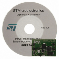
EVAL6920DB1 STMicroelectronics, EVAL6920DB1 Datasheet - Page 5

EVAL6920DB1
Manufacturer Part Number
EVAL6920DB1
Description
EVAL BOARD FOR L6920DB
Manufacturer
STMicroelectronics
Type
DC/DC Switching Converters, Regulators & Controllersr
Specifications of EVAL6920DB1
Main Purpose
DC/DC, Step Up
Outputs And Type
1, Non-Isolated
Voltage - Output
3.3V or 5V
Current - Output
100 ~ 400mA
Voltage - Input
0.8 ~ 3.6 V
Regulator Topology
Boost
Frequency - Switching
1MHz
Board Type
Fully Populated
Utilized Ic / Part
L6920
Input Voltage
0.6 V
Output Voltage
1.8 V
Dimensions
17.5 mm to 12.6 mm
Product
Power Management Modules
Lead Free Status / RoHS Status
Lead free / RoHS Compliant
Power - Output
-
Lead Free Status / Rohs Status
Lead free / RoHS Compliant
For Use With/related Products
L6920DB
Other names
497-5503
AN2206
1.4
1.5
1.6
Table 2.
Inductor selection
Usually, inductors ranging between 2 µH to 10 µH satisfy most application requirements.
However, small-value inductors are physically smaller and guarantee a faster response to
load transients.
Inductor size also affects the maximum current deliverable to the load. A low series
resistance is suggested if very high efficiency values are needed. In any case, the saturation
current of the choke should be higher than the peak current limit of the device (800 mA typ.).
Good surface-mount inductors are available from COILCRAFTS, COILTRONICS and other
sources (see
Table 3.
Switching frequency
The control loop of the L6920DB is based on a Minimum OFF-time and a Maximum ON-time
(see datasheet). This means that the switching frequency is not fixed, but changes in order
to keep the output voltage regulated. The maximum reachable value is approximately 1MHz.
The frequency value depends on the inductor value, input and output voltage, and the load.
Low battery detection
The L6920DB includes a low battery detection comparator. The threshold is V
and a hysteresis is added to avoid oscillations when input crosses the threshold slowly. The
Low Battery Output (LBO) is an open drain, so a pull-up resistor, R3, is required for proper
use. Adding a resistor divider at the Low Battery Input (LBI) pin gives the user the ability to
set at which value of V
Equation 1
SANYO POSCAP
Manufacturer
PANASONIC
Manufacturer
Coiltronics
Panasonic
Coilcraft
Distributor's capacitor main list (continued)
Distributor's inductor main list
Table
3).
BATT
TPA/B/C
EEFCD
Series
the (LBO goes high. The relationship is showed below:
V
LPO1704
LPO6610
ELL6SH
ELL6RH
Series
BATT TH
SD10
SD12
–
Cap value (µF)
22 to 230
22 to 47
=
1.23V
Inductor value (µH)
•
⎛
⎝
2.2 to 6.2
2.2 to 10
2.2 to 10
3.3 to 10
10 to 22
5.1 to10
1
+
Rated voltage (V)
R1
------- -
R2
⎞
⎠
6.3
6.3
Application information
Saturation current (A)
0.85 to 1.4
1.1 to 1.55
0.9 to 1.6
0.9 to 1.5
0.9 to 1.6
0.9 to 1.5
ESR (mΩ)
REF
50 to 700
40 to 80
voltage
5/11


