EVALTSM1052 STMicroelectronics, EVALTSM1052 Datasheet
EVALTSM1052
Specifications of EVALTSM1052
Available stocks


Related parts for EVALTSM1052


EVALTSM1052 Summary of contents
Page 1
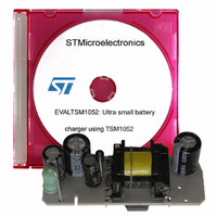
... EVALTSM1052: Ultra small battery charger using TSM1052 Introduction This document describes a low power adapter that can be used in travel battery charger applications. It uses the new Constant Voltage Constant Current (CVCC) controller TSM1052, which is housed in one of the smallest packages available (SOT23-6L). Thanks to its low consumption and low operating voltage, good electrical performance is achieved. ...
Page 2
Contents Contents 1 Adapter features . . . . . . . . . . . . . . . . . . . . . . . . . . . . . . . . . . . ...
Page 3
... AN2448 List of figures Figure 1. EVALTSM1052 demo board . . . . . . . . . . . . . . . . . . . . . . . . . . . . . . . . . . . . . . . . . . . . . . . . . 1 Figure 2. Electrical diagram . . . . . . . . . . . . . . . . . . . . . . . . . . . . . . . . . . . . . . . . . . . . . . . . . . . . . . . . . 5 Figure 115 Vrms - Figure 230 Vrms - Figure 5. Maximum supply voltages . . . . . . . . . . . . . . . . . . . . . . . . . . . . . . . . . . . . . . . . . . . . . . . . . . 9 Figure 6. Minimum supply voltages . . . . . . . . . . . . . . . . . . . . . . . . . . . . . . . . . . . . . . . . . . . . . . . . . . . 9 Figure 115 V - no-load . . . . . . . . . . . . . . . . . . . . . . . . . . . . . . . . . . . . . . . . . . . . . . . . . . . . Figure 8 ...
Page 4
Adapter features 1 Adapter features 1.1 Main characteristics ● Input: – 264 Vrms in – ● Output: – 5.1Vdc ± 2% – 600 mA – Cable drop compensation (0.33 mV/mA) ● ...
Page 5
AN2448 Figure 2. Electrical diagram Adapter features 5/21 ...
Page 6
Adapter features 1.2 Circuit description The circuit used implements a flyback topology, which is ideal for a low power, low cost isolated converter. At primary side a VIPer12A-E has been used. This IC includes a current mode PWM controller and ...
Page 7
AN2448 2 Electrical behavior Figure 3 and Figure 4 load. The converter operates in DCM at both 115 Vrms and 230 Vrms: Figure 115 Vrms - CH1: VIPer12A-E supply voltage (yellow) CH2: VIPer12A-E feedback ...
Page 8
Electrical behavior Figure 230 Vrms - CH1: VIPer12A-E supply voltage (yellow) CH2: VIPer12A-E feedback pin (light blue) CH3: VIPer12A-E drain voltage (purple) Due to the forward supply, the V is nearly double at 230 ...
Page 9
AN2448 Figure 5. Maximum supply voltages CH1: output voltage (yellow) CH2: VIPer12A-E supply voltage (light blue) CH3: TSM1052 supply voltage (green) Figure 6. Minimum supply voltages CH1: output voltage (yellow) CH2: VIPer12A-E supply voltage (light blue) CH3: TSM1052 supply voltage ...
Page 10
Electrical behavior Let's see what happens at the extreme conditions: no load and short circuit. During no load conditions, the circuit operates in burst mode allowing an input power of less than 300 mW over the whole input voltage range. ...
Page 11
AN2448 Figure 115 V in CH1: output voltage (yellow) CH2: VIPer12A-E drain pin (purple) CH3: TSM1052 supply voltage (green) Figure 10 230 V in CH1: output voltage (yellow) CH2: VIPer12A-E drain pin (purple) CH3: output ...
Page 12
Electrical performance With the circuit used in this evaluation board, when the output current has rapid variation from maximum to zero and the input voltage is low ( < 105 V supply for about 400-500 ms. The output voltage thereby ...
Page 13
AN2448 Figure 11. Efficiency vs. output current 75.0% 70.0% 65.0% 60.0% 55.0% 50.0% 45.0% 40. indicated in Table complies with the more restrictive standards (European Code Of Conduct). Table 3. No-load consumption Value Pin [W] V [V] OUT ...
Page 14
Electrical performance The effect of the cable drop compensation is also worthy of note. voltage at various load amounts measured at the output connector, after the output cable. 115 V and 230 V ac the output voltage is nearly constant ...
Page 15
AN2448 Figure 14. Power down at 230 Electrical performance CH1: output voltage (yellow) CH3: rectified input voltage (purple) 15/21 ...
Page 16
Conducted noise measurements (pre-compliance test) 4 Conducted noise measurements (pre-compliance test) Figure 15 and Figure 16 nominal voltages with peak detection and considering only the worst phase. The measurements have a good margin with respect to the limits (stated in ...
Page 17
AN2448 5 Thermal measurements A thermal analysis of the board was performed using an IR camera. The results are shown in Figure 17 and load condition (Iout = 600 mA °C for both figures AMB Emissivity = ...
Page 18
Thermal measurements Figure 18 230 V in Table 6. Key component temperatures at 230 V Point 18/21 - full load - bottom and top sides ac ac Temperature [ºC] 70.4 72.7 ...
Page 19
... AN2448 6 BOM Table 7. EVALTSM1052 bill of material Ref C10 C11 IC1 IC2 IC3 R10 R11 Chip resistor 0.33 Ohm ±1% 200 ppm R12 R13 Description Electr.cap. 2.2 µF 400 V 105ºC SEK Electr.cap. 4.7 µF 400 V 105ºC SEK Electr.cap. 33 µ 105ºC Electr.cap. 470 µ ...
Page 20
... PCB layout Table 7. EVALTSM1052 bill of material (continued) Ref R14 R15 TR1 7 PCB layout Figure 19. THT components placing (top side) Figure 20. SMT components placing (bottom side) and copper tracks 8 Revision history Table 8. Revision history Date 04-Jul-2007 20/21 Description Chip resistor 22 K ±5% ...
Page 21
... AN2448 Information in this document is provided solely in connection with ST products. STMicroelectronics NV and its subsidiaries (“ST”) reserve the right to make changes, corrections, modifications or improvements, to this document, and the products and services described herein at any time, without notice. All ST products are sold pursuant to ST’s terms and conditions of sale. ...