SOT23-3EV-VREG Microchip Technology, SOT23-3EV-VREG Datasheet - Page 11
SOT23-3EV-VREG
Manufacturer Part Number
SOT23-3EV-VREG
Description
BOARD EVAL VOLT REG SOT23-3
Manufacturer
Microchip Technology
Datasheet
1.SOT23-3EV-VREG.pdf
(22 pages)
Specifications of SOT23-3EV-VREG
Channels Per Ic
1 - Single
Board Type
Partially Populated
Utilized Ic / Part
SOT-23-3 Package
Silicon Manufacturer
Microchip
Application Sub Type
Voltage Regulator
Kit Application Type
Power Management - Voltage Regulator
Silicon Core Number
MCP1701A, MCP1702, MCP1703
Kit Contents
Board
Lead Free Status / RoHS Status
Lead free / RoHS Compliant
Current - Output
-
Voltage - Output
-
Voltage - Input
-
Operating Temperature
-
Regulator Type
-
Lead Free Status / Rohs Status
Lead free / RoHS Compliant


2.1
2.2
2.3
© 2008 Microchip Technology Inc.
INTRODUCTION
FEATURES
GETTING STARTED
Chapter 2. Installation and Operation
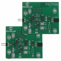
The SOT23-3 Voltage Regulator Evaluation Board is designed to be used to facilitate
the evaluation of Microchip’s voltage regulators, or to be used as a stand-alone voltage
regulator board. Jumpers have been placed on the board to ease the test of the
specific voltage regulator parameters.
The SOT23-3 Voltage Regulator Evaluation Board kit comes with a 1 μF ceramic input
and output capacitor soldered to the board. The board has two unpopulated resistor
locations that may be used for loads.
The SOT23-3 Voltage Regulator Evaluation Board has the following features:
• Input and Output headers for future connection to Line Step and Load Step
• Ample testpoints to attach multimeters, power supplies, and loads
• Jumper to select ground current measurement
• Jumper to connect output load resistor
• Jumper to connect input capacitor to circuit
• Jumper to select one of two device pinouts
The SOT23-3 Voltage Regulator Evaluation Board is fully assembled and tested. All
that is required for operating is a voltage regulator supplied by the user, and a supply
voltage source. Some of the tests that may be completed using the SOT23-3 Voltage
Regulator Evaluation Board are described in the next subchapters.
2.3.1
For all tests, JP2 and JP5 must be set to select the desired device and footprint.
JP2 - connect pins
JP5 - connect pins
modules
Jumpers
Device Pinout Selection (For All Tests)
EVALUATION BOARD USER’S GUIDE
SOT23-3 VOLTAGE REGULATOR
U1 Footprint
2-3
2-3
U2 Footprint
1-2
1-2
DS51785A-page 7
Related parts for SOT23-3EV-VREG
Image
Part Number
Description
Manufacturer
Datasheet
Request
R


Part Number:
Description:
SOT23/E/ECONRST 3.3V 5% CMOS OUT SOT23 T&R
Manufacturer:
Maxim Integrated Products
Datasheet:
Part Number:
Description:
SOT23-6/A�/20MBPS +3.3V SOT23 RS-485/RS-422 TRANSMITTERS
Manufacturer:
Maxim Integrated Products
Datasheet:
Part Number:
Description:
SOT23-8/A�/Low-Voltage, SOT23, �P Supervisors
Manufacturer:
Maxim Integrated Products
Part Number:
Description:
SOT23/E/ECONORST 3.3V-10% W/PBRST SOT23 T&R
Manufacturer:
Maxim Integrated Products

Part Number:
Description:
SOT23, Low-Power uP Supervisory Circuits with Battery Backup and Chip-Enable Gating
Manufacturer:
Maxim Integrated Products
Datasheet:
Part Number:
Description:
SOT23, Low-Power uP Supervisory Circuits with Battery Backup and Chip-Enable Gating
Manufacturer:
Maxim Integrated Products
