EK57 Cirrus Logic Inc, EK57 Datasheet - Page 2
EK57
Manufacturer Part Number
EK57
Description
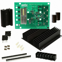
KIT EVAL FOR MP108FD/MP111FD
Manufacturer
Cirrus Logic Inc
Series
Apex Precision Power™r
Specifications of EK57
Channels Per Ic
1 - Single
Amplifier Type
Power
Output Type
Single-Ended
Board Type
Bare (Unpopulated)
Utilized Ic / Part
MP108FD, MP111FD
Product
Amplifier Modules
Description/function
Audio Amplifiers
For Use With/related Products
MP108FD, MP111FD
Lead Free Status / RoHS Status
Contains lead / RoHS non-compliant
Operating Temperature
-
Current - Output / Channel
-
Voltage - Supply, Single/dual (±)
-
-3db Bandwidth
-
Slew Rate
-
Current - Supply (main Ic)
-
Lead Free Status / RoHS Status
Lead free / RoHS Compliant, Contains lead / RoHS non-compliant
Other names
598-1470
EK57
EK57


EK57
ASSEMBLY CONT.
15. Use #8 X 1" sheet metal screws (not provided) to mount
FIGURE 1: SCHEMATIC DIAGRAM
2
1
3
4
5
2
the amplifier’s pins until the four spacer grommets at the
four corners of the PCB touch the heatsink. At this point
the PCB should not be bowed.
the PCB to the heat sink at the four spacer-grommets.
VIEW FROM PCB COMPONENT SIDE
-IN
34
+IN
33
C5
GND
TP
32
1
BPLT
NC
31
TERMINAL STRIP TERMINALS
2
PCB AMPLIFIER TERMINALS
ASSESSORY TERMINALS
PCB WIRING TERMINALS
GND
-Vb
30
3
C6
+Vb
NC
29
4
+Ilim
CC1
28
5
C2
C1
+
R
LIM
CC2
-Ilim
27
6
NC
NC
26
7
+Vb
P r o d u c t I n n o v a t i o n F r o m
-Vb
25
8
NC
NC
24
9
C4
+
C3
16. Inspect the assembly from the side and check that the PCB
17. Hook up power and signals as necessary. The amplifier
is not bowed toward the heat sink. If the PCB is bowed use
a small tool to carefully pry the PCB away from the heat
sink until the PCB is flat.
is now ready for testing.
NC
NC
10
23
OUT
OUT
11
22
OUT
OUT
12
21
OUT
OUT
13
20
+Vs
14
-Vs
19
+Vs
-Vs
15
18
+Vs
16
-Vs
17
TS1
EK57U
SPARE
+Vs
+Vb
OUT
GND
-Vs
-Vb
Related parts for EK57
Image
Part Number
Description
Manufacturer
Datasheet
Request
R

Part Number:
Description:
Development Kit
Manufacturer:
Cirrus Logic Inc
Datasheet:
Part Number:
Description:
Development Kit
Manufacturer:
Cirrus Logic Inc
Datasheet:


Part Number:
Description:
High-efficiency PFC + Fluorescent Lamp Driver Reference Design
Manufacturer:
Cirrus Logic Inc
Datasheet:
Part Number:
Description:
Development Kit
Manufacturer:
Cirrus Logic Inc
Datasheet:
Part Number:
Description:
Development Kit
Manufacturer:
Cirrus Logic Inc
Datasheet:

Part Number:
Description:
Development Kit
Manufacturer:
Cirrus Logic Inc
Datasheet:
Part Number:
Description:
Development Kit
Manufacturer:
Cirrus Logic Inc
Datasheet:
Part Number:
Description:
Development Kit
Manufacturer:
Cirrus Logic Inc
Datasheet:
Part Number:
Description:
Development Kit
Manufacturer:
Cirrus Logic Inc
Datasheet:

Part Number:
Description:
EVALUATION BOARD FOR CS8427
Manufacturer:
Cirrus Logic Inc
Datasheet:

Part Number:
Description:
BOARD EVAL FOR CS8416 RCVR
Manufacturer:
Cirrus Logic Inc
Datasheet:

Part Number:
Description:
EVALUATION BOARD FOR CS8420
Manufacturer:
Cirrus Logic Inc
Datasheet:

Part Number:
Description:
KIT DEVELOPMENT EP9315 ARM9
Manufacturer:
Cirrus Logic Inc
Datasheet:

Part Number:
Description:
KIT DEVELOPMENT EP9302 ARM9
Manufacturer:
Cirrus Logic Inc
Datasheet: